You are using an out of date browser. It may not display this or other websites correctly.
You should upgrade or use an alternative browser.
You should upgrade or use an alternative browser.
Unfolding box to flat sheet
- Thread starter pdusp2
- Start date
@pdusp2 It looks like you did the trick. Is your unfolding also written in C++?
I have attached a couple of models that you may want to try. Curious to hear back about your results!
I have attached a couple of models that you may want to try. Curious to hear back about your results!
Attachments
Thank you,
You have made me very happy with them.
I loved OpenCascade, but I'm still a beginner.
My plan is to take one wall from the 3D object, as if I were putting flat paper on it,
from this model finds all adjacent faces and edges,
I convert the cylinder's segments into flat elements, and all the walls I bring all the pieces to the largest flat plane, to its normal vector, and finally save it to the Step file.
I use recursion to navigate the tree, and everything is in C++ MFC. I miss someone to talk to, I'm very lonely in this programming :-(
For simple models it already works, but for more advanced models there are still a few problems.
Finally, I have to remember the direction of bending the sheet metal and use the tangent to determine the plane replacing the cylinder's section.
Have a nice day
Piotr
You can definitely talk about sheet metal here, on this forum. We've been working on such kind of an algorithm starting from 2017, and it always has something to fix and improve. What is especially interesting to me right now is bend simulation: something close to what OSH Cut does: you upload a part, it gets unfolded and then you fold it back to see if there are any collisions between the folded state of geometry and a punch. Another challenging topic is 2D nesting. This is where I'd love to learn from someone experienced.
I am guessing you guys are doing an exact unbend. Meaning: that from a predefined die plane walking faces searching for cylinders and planes. rotating and translating, with bend allowance, cylindrical dependent geometry. My first question is: What do you do when some 'bozo' in the data distribution network has done some translation where all the analytic surfaces(planes, cylinders) have been replaced with bspline representations? My second question is: Have you incorporated, or have another algo, for shapes that are beyond simple straight bends?
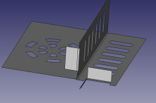
I put some work into stamping die related functionality into cadseer(see picture), but never did anything for the simple straight bend parts. For the more complicated shapes, I did find libIGL that has a ARAP algo that has been good for the limited testing I have done. I will attach the input shape(one side of metal) and the result.
Oh wait ... we have to have a carrier to bind the strip together.
Oh wait ... we have to cam pierce that hole so you will have to twist the part 15 degrees.
Oh wait ... if we twist it 30 degrees we will use the same stock usage but have wider coil and less pitch. fewer coil changes = money.
Oh wait ... we are going to use a different press and now we want a 2 out.
 my point being: IMHO: There are so many factors beyond the geometry that are out of your control that you can't 'solve' it. The only thing you can do is provide efficient tools for a human to finalize it. I have 5 years building and 15 years designing stamping dies and you know I am not short on opinions, just ask. If I can help, I will.

I put some work into stamping die related functionality into cadseer(see picture), but never did anything for the simple straight bend parts. For the more complicated shapes, I did find libIGL that has a ARAP algo that has been good for the limited testing I have done. I will attach the input shape(one side of metal) and the result.
2D nesting is easy. Just rotate the part until you minimize stock usage.You can definitely talk about sheet metal here, on this forum. We've been working on such kind of an algorithm starting from 2017, and it always has something to fix and improve. What is especially interesting to me right now is bend simulation: something close to what OSH Cut does: you upload a part, it gets unfolded and then you fold it back to see if there are any collisions between the folded state of geometry and a punch. Another challenging topic is 2D nesting. This is where I'd love to learn from someone experienced.
Oh wait ... we have to have a carrier to bind the strip together.
Oh wait ... we have to cam pierce that hole so you will have to twist the part 15 degrees.
Oh wait ... if we twist it 30 degrees we will use the same stock usage but have wider coil and less pitch. fewer coil changes = money.
Oh wait ... we are going to use a different press and now we want a 2 out.
my point being: IMHO: There are so many factors beyond the geometry that are out of your control that you can't 'solve' it. The only thing you can do is provide efficient tools for a human to finalize it. I have 5 years building and 15 years designing stamping dies and you know I am not short on opinions, just ask. If I can help, I will. Attachments
Yep, it's exactly this "origami" with sole deformations centered at bends and fully driven by K-factor.I am guessing you guys are doing an exact unbend.
If that's the case, there is an option to turn spliny geometries into canonical ones: https://analysissitus.org/features/features_recognize-analytical.htmlWhat do you do when some 'bozo' in the data distribution network has done some translation where all the analytic surfaces(planes, cylinders) have been replaced with bspline representations?
It can be done automatically as a preprocessing stage, although I normally prefer to avoid it, and the only preprocessing stage that is activated by default is face maximization (i.e., your favorite "unify same domain").
Do you mean surfaces of double curvature (non-zero Gaussian)? Nope, and I have quite some negative experience trying to adopt unwrapping with deformations for ship building (cold rolling vs line heating), which was never quite what users expected to see. I guess ExactFlat solves this problem accurately (I assume this because they have the entire company selling this stuff and they have existed for quite a while already), but I've never used their tools.My second question is: Have you incorporated, or have another algo, for shapes that are beyond simple straight bends?
Thanks for the reference to libIGL and ARAP. It's a shame I have never heard about it. Do they have some published papers to read on? The unfolded shape looks nice, although I'm kinda never sure if the deformations are realistic enough. But I guess you validated the computed strains. Do they look physically correct?
The algorithm that we have was inspired by the recognize & unfold functionality in SpaceClaim, which is pretty standard and exists in many other tools like Fusion and FreeCAD (this Python script). So we targeted a specific class of models, although I can say that even in the narrow class of models, you have quite a few edge cases to deal with.I put some work into stamping die related functionality into cadseer(see picture), but never did anything for the simple straight bend parts.
Hah, you know what. We are building our CAM feature recognizer, and we have exactly this situation with all potential users. Like you recognize a feature here and there, then group all CAM features into something you call a "setup" and after that, you get several completely opposite feedbacks from technologists. Some are saying that they will make this part from this and that direction, while others will argue and propose to flip a part, reclamp it "like this" and use a different tool. The only thing they would agree on is that your automatic approach is nonsense and has nothing to do with realityThere are so many factors beyond the geometry that are out of your control that you can't 'solve' it. The only thing you can do is provide efficient tools for a human to finalize it.
That happens even in sheet metal, but in CNC the automatic recognition is just a disaster. I agree, you should build what you can on geometry and let humans do the rest, but humans always want a magic button solution that would work exactly as they wish (even when one case contradicts another).Appreciate that, thank you.I have 5 years building and 15 years designing stamping dies and you know I am not short on opinions, just ask. If I can help, I will.
Thanks, I will check it out as that is a common problem out "in the wild."If that's the case, there is an option to turn spliny geometries into canonical ones: https://analysissitus.org/features/features_recognize-analytical.html
It can be done automatically as a preprocessing stage, although I normally prefer to avoid it, and the only preprocessing stage that is activated by default is face maximization (i.e., your favorite "unify same domain").
I have never used ExactFlat, but have experience with similar software products. My industry knowledge is about 10 years old now, so processes or best practices maybe different now, but I will layout design process from my experience. I will contrast the design process of "your simple part" vs "my complex part". With one of "your simple parts" once the flat blank has been produced, the designer can finalize the initial blanking stations. With one of "my complex parts" a produced blank, say via ARAP, is not expected to be accurate enough to establish the initial blanking stations. What we need at this stage, is just something close enough to establish stock width and pitch. Then design of the forming stations happen and we can then use the form models and the approximate blank and do multiple FEA forming simulations to refine the blank shape. The resultant blank from the FEA simulations can then be used to finalize the initial blanking stations. Hopefully that made sense. That process I described was done for the part that I posted. I took the final FEA produced blank and compared to the ARAP produced blank and I was very pleased with the ARAP approximation. I will see if I can find that overlay.Do you mean surfaces of double curvature (non-zero Gaussian)? Nope, and I have quite some negative experience trying to adopt unwrapping with deformations for ship building (cold rolling vs line heating), which was never quite what users expected to see. I guess ExactFlat solves this problem accurately (I assume this because they have the entire company selling this stuff and they have existed for quite a while already), but I've never used their tools.
Thanks for the reference to libIGL and ARAP. It's a shame I have never heard about it. Do they have some published papers to read on? The unfolded shape looks nice, although I'm kinda never sure if the deformations are realistic enough. But I guess you validated the computed strains. Do they look physically correct?
The libIGL tutorial page has a good write up with some references.
I have been quietly following along your journey and I was hoping things were going to be better for you than me. None of what you describe, surprises me.Hah, you know what. We are building our CAM feature recognizer, and we have exactly this situation with all potential users. Like you recognize a feature here and there, then group all CAM features into something you call a "setup" and after that, you get several completely opposite feedbacks from technologists. Some are saying that they will make this part from this and that direction, while others will argue and propose to flip a part, reclamp it "like this" and use a different tool. The only thing they would agree on is that your automatic approach is nonsense and has nothing to do with reality
Last edited:
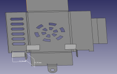
I took the final FEA produced blank and compared to the ARAP produced blank and I was very pleased with the ARAP approximation. I will see if I can find that overlay.

The white blank is what was produced via the FEA process and ultimately put into the tool. The black is what libIGL ARAP produced. I was actually quite surprised it was that close.
Alright, clear then. We were working on a specific unwrapping algorithm with deformations, more or less based on the attached paper. The results were around Ok-ish for ship plates but completely off for automotive stamped parts. Which is explainable, of course. Btw, we also used Eigen.With one of "my complex parts" a produced blank, say via ARAP, is not expected to be accurate enough to establish the initial blanking stations. What we need at this stage, is just something close enough to establish stock width and pitch.
Looking at IGL and its functions, I'm getting the feeling that the computer graphics community has contributed quite a lot to open source engineering tools. E.g., geodesic paths by Keenan Crane, remeshing techniques available publicly, ARAP, etc. -- all these tools close some sensitive gaps that we addressed manually some 10 years ago. Now you can go and pick up a header-only algorithm. Amazing.
Attachments
Well yeah! I can't pull this stuff off.Now you can go and pick up a header-only algorithm. Amazing.
Before I found libIGL and ARAP, I was trying to work my way through this paper. Transferring equations from a paper to working code is beyond me. I think a lot of this is involved in texture wrapping for game development, which is a huge industry. Luckily, for me, some of that investment has been open sourced.Another thing I checked out briefly was boundary first flatten. paper, repo. It has been a few years now, but at the time I didn't see a way to lock down faces, like I could with libIGL/ARAP. Maybe I missed it, or it has been added since, but we need to anchor faces/triangles to simulate forming pressure pads to help with accurate blank prediction.
Have you ever been exposed to forming simulations? I have code-aster/salome mecca on my mile long list of tech to check out.
Nope. My only relation to numerical simulation was developing some pre-/post-processors around structural analysis, CFD, etc, while all the hard work was either done by the solver itself or by people working on the solver side of the equation. For example, we are now developing a module of Salome to interface with OpenFOAM (via TCAE). Later this year, we will also touch Code_Aster to build it in docker with Petsc enabled, but our part of the deal is pure technical. E.g., just building Salome in debug mode requires weeks of desperate trial and error.Have you ever been exposed to forming simulations? I have code-aster/salome mecca on my mile long list of tech to check out.
just building Salome in debug mode requires weeks of desperate trial and error.
Wow! Sorry I have to ask. Why is that so hard? Is a release build much smoother?
What is hard is to follow poor documentation while having almost zero support and a hell of dependencies. To avoid release + debug mix (on Windows), we try to build all the Salome's 3-rd parties, and there are just too many. Actually, it is theoretically possible to survive with release build with all existing precompiled dependencies, but in this case, you'll be unable to step into the in-house GUI classes of Salome (what they call SUIT = Salome UI Toolkit). In the long run, we want to be able to debug whichever place in Salome we want, i.e., to have full control over the code base. I'm unpleasantly surprised how complicated this process turns out to be.Wow! Sorry I have to ask. Why is that so hard? Is a release build much smoother?
I took a quick look and ... yeah ... no. 3 things come to mind for me.I'm unpleasantly surprised how complicated this process turns out to be.
1) 'remember the vasa'
2) Do I really need any of this and can I tear it out?
3) Maybe they should just create their own linux distro.
Not that it helps, but you have my sympathy. Good luck.