Profile part recognition

Dirk S.

CAD practitioner
Hello,

I am looking for some guidance to recognize parts, I-beams in particular. What I would like to achieve is to recognize it's an I-beam and to determine its dimensions like height, width, radius and thickness (flange and web)

I can make use of the fact that the parts always should have concave fillets (radii) along the direction of the profile.

What I have tried so far. It looked the easiest to first make it a 2D problem instead of a 3D problem.
- Use the direction of the cylindrical surface with the longest length as a projection direction and then project with HLRAlgo_Projector and then try to make a wire from the projected edges. I could not make this work reliably as it is hard to determine which edges need to be part of the wire. Also, the projected cylindrical surfaces could result in edges of type b-spline instead of circles.
- Use BOPAlgo_Section to generate a section with as a tool a face defined by a plane with the direction of the profile. The resulting edges are easily converted to a wire and the edges could still be analytical. The problem with this approach is where to do the section. The beam could have holes in it which messes up the section result if the section plane intersects with a hole.

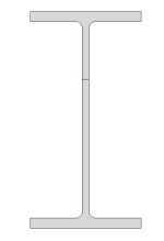
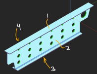
Any suggestions on how to deal with this? Should I look into feature recognition with the help of an aag? The below pictures are just an example.

Thanks,
Dirk

I-beam.pngleft view.png
 

Dirk S.

CAD practitioner
Thanks Quaoar! My section approach looks like what you describe in your overview. Could you elaborate how you went from a section to a pixmap and compare with an image? If I understood correctly.
 

Quaoar

Administrator
Staff member
The algorithm extracts the reference section as a polyline (as it slices the model mesh to perform quickly). Then this polyline is turned into a `TopoDS_Face` face and pixelated with the following function (depends on Analysis Situs):

Code:
bool Utils::Graphics::Pixelate(const TopoDS_Face&                  face,
                               const int                           numBins,
                               const std::string&                  dumpFilename,
                               Handle(asiAlgo_UniformGrid<float>)& grid,
                               ActAPI_ProgressEntry                progress,
                               ActAPI_PlotterEntry                 plotter)
{
  if ( face.IsNull() )
    return false;

  // Sample the face.
  asiAlgo_SampleFace sampleFace(face, progress, plotter);
  //
  sampleFace.SetSquare(true);
  sampleFace.SetPmcAlgo(asiAlgo_SampleFace::PmcAlgo_Discrete);
  //
  if ( !sampleFace.Perform(numBins) )
  {
    progress.SendLogMessage(LogErr(Normal) << "Failed to sample the face.");
    return false;
  }
  //
  grid = sampleFace.GetResult();

  Image_AlienPixMap pixmap;

  // Use Image_Format_BGR since it's the pixel format of the minimal size supported by Windows BMP Native Codec
  // and available through OCCT, see the following for more detail:
  // WICPixelFormatGUID Image_AlienPixMap::convertToWicFormat()
  // https://docs.microsoft.com/en-us/windows/win32/wic/-wic-codec-native-pixel-formats#bmp-native-codec
  pixmap.InitZero(Image_Format::Image_Format_BGR, numBins, numBins);
  pixmap.SetTopDown(true);

  // set a color for each pixel - it's either black or white
  for ( int rowIter = 0; rowIter < numBins; ++rowIter )
  {
    for ( int colIter = 0; colIter < numBins; ++colIter )
    {
      const float isIn = grid->pArray[rowIter][colIter][0];
      pixmap.ChangeRawValue(rowIter, colIter)[0] = isIn ? 0 : 255;
      pixmap.ChangeRawValue(rowIter, colIter)[1] = isIn ? 0 : 255;
      pixmap.ChangeRawValue(rowIter, colIter)[2] = isIn ? 0 : 255;
    }
  }

  return pixmap.Save(dumpFilename.c_str());
}

This code is essentially just sampling the face with the prescribed grain size and assigning it to black & white colors. You asked how these images are matched, but here I cannot help because this matching magic was done by another team, and I've never seen it in action. I'm just thinking that image matching makes perfect sense as long as you can feed it with a monochrome bitmap image of fixed dimensions, which looks like an ideally prepared piece of data for this sort of tool.

But, stepping aside from images, it's also possible to recognize the shape analytically. You have an I-profile (or H-profile). For this kind of profile, the algorithm we developed would return 4 sides:

1711034739687.png

These sides are reported in a JSON like this:

Code:
"sheets": [
              {
                "faceIds": [23, 35, 44],
                "angles": [
                  {
                    "faceIds": [23, 35],
                    "angle": -90
                  },
                  {
                    "faceIds": [23, 44],
                    "angle": -90
                  }
                ]
              },
              {
                "faceIds": [25, 28, 38],
                "angles": [
                  {
                    "faceIds": [25, 28],
                    "angle": -90
                  },
                  {
                    "faceIds": [25, 38],
                    "angle": -90
                  }
                ]
              },
              {
                "faceIds": [30],
                "angles": [
                ]
              },
              {
                "faceIds": [42],
                "angles": [
                ]
              }
            ]
          }

By looking at these pairs of faces [23, 35], [23, 44] and the dihedral angles between them (negative for concave, positive for convex), it is easy to put together a simple rule that would deduce it's an H/I-shaped profile.

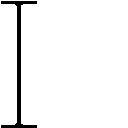
Here's the bitmap:

ssv-test-profile_05_0-1-1-1_1_slice.png

The STEP file is also attached.
 

Attachments

  • ssv-test-profile_05.step
    65.7 KB · Views: 1

Quaoar

Administrator
Staff member
I forgot to mention one trick. To decrease the chances that inner holes/cutouts mess up your section, you may want to consider defeaturing them. This can be done very quickly and reliably for isolated features, and non-isolated holes may remain as they tend to be not very common. We apply such a trick and it turns out to be helpful.

After defeaturing, we take 10-15 slices along the profile axis (which you already know from the cylinder axis) and choose the largest one (although, to be more precise, we rather use a simple voting mechanics to choose the slice with the most common area). Then we project all other slices to the chosen one to verify the prismaticity of the part.
 

Dirk S.

CAD practitioner
Hi Quaoar, if you don't mind me asking. How do you determine the number of sheets / sides?

By using the normals of the planes and then find pairs with opposite direction?
 

Quaoar

Administrator
Staff member
In principle, yes. In more detail, all parallel planes are matched up, assigned to the thickness value (which you normally get out of the matching logic), and then the algorithm decides which thickness to take as a reference. All pairs assigned to that thickness are taken as sheet faces. Already here, it should be possible to set some limits on the thickness. Are you working on a general solution that would work for any type of profile, or is it specialized for I-beams?
 
Top