Hello
@soupyx,
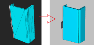
In you sample you have no edges, only faces with triangulation on them. So, in the mode that you use for AIS_Shape, we see this triangulation shown over the model.
There is lack of information from visualization point of view to separate only lines as shown on the right image. Moreover, this model has only six faces (bottom, top, back, front and faces on sides) So, we have no here the separated faces to see them like them are divided and bounded with edges on the right. It’s only upper values on the same face, not a separate face at all, so lines shown on the right are not the face boundary.
The first proposal here is to implement some algorithm to preprocess triangulation and remove from the triangulation not necessary points (if for example angle is too small between neighbor triangles). After, give this prepared data to AIS_Shape as you do now. If you choose these way, it might be useful have a look at HLR algorithms in OCCT and get some hints from it.
Another solution is do not visualize triangles at all using flag in presentation attributes (not very interesting solution, but a cheap one and OCCT has this mode)
Also, I would investigate deeper MeshVS package. This OCCT package proposes presentation ‘MeshVS_Mesh’ for mesh kind of data. If you have a look at it, I propose starting investigation from display modes described in MeshVS_DisplayModeFlags. But on my light investigations, there is no your case implemented from the box(.
I tried to find some OpenGL shader implemented in OCCT for your case. And found outline the mode possibility managed through ‘SetDrawSilhouette’ in graphic aspect. There is a DRAW command to try it, if you'd like. But the result is only external boundaries are visualized, not your case. This mode has no internal edges as shown on the right image. May be it's worth searching another OpenGl shader and add it to OCCT visualization to cover your case? OCC gives a possibility to add new shaders into visualization.
Sorry, it's not the solution ready, only some thoughts about what to try)
Share with us results of your investigations, it's interesting what would be the solution for you.
Regards, Natalia


