Hello together,
I am struggeling now since days. Doing research, reading, trying to find working code & understanding the found code.
Thing is, I am complete new to OCCT (and also C++).
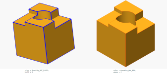
I am using pythonocc. I can read STEP and also creating a thumbnail of it with help of pythonocc (with reset face colors).
But I want to increase the line width of all edges as well, also I'd like to control the edge color.
(the code is basically copy & paste from around the internet)
Here is a part of my python code for creating the thumbnail. The shape was read from a .stp file with STEPCAFControl_Reader and XCAFDoc_DocumentTool.
For sure I am doing something wrong.
Very likely "changing" edges just works differently. I don't even know if I can just create such an aspect from out of nowhere and assign it. Also even if, I don't know where to assign it.
Until now I didn't find any piece of documentation that explains how the pieces are put together correctly...
Any hints, suggestions, corrections, help? Thanks very much!
Btw. setting width via FaceBoundaryAspect BEFORE adding the shape helps already with the edge width. But the same "trick" (that I don't understand) doesn't work for the color...
I am struggeling now since days. Doing research, reading, trying to find working code & understanding the found code.
Thing is, I am complete new to OCCT (and also C++).
I am using pythonocc. I can read STEP and also creating a thumbnail of it with help of pythonocc (with reset face colors).
But I want to increase the line width of all edges as well, also I'd like to control the edge color.
(the code is basically copy & paste from around the internet)
Here is a part of my python code for creating the thumbnail. The shape was read from a .stp file with STEPCAFControl_Reader and XCAFDoc_DocumentTool.
Python:
    def __init__(self, request_id: str, file: str) -> None:
        self.doc = TDocStd_Document(TCollection_ExtendedString("_output"))
        self.file = file

        self.request_id = request_id

        self.thumbnail_dir = f"./tmp_thumbnail/{request_id}"
        os.makedirs(self.thumbnail_dir, exist_ok=True)

        self.thumbnail_display: Viewer3d = self.__create_display()
        self.thumbnail_context: AIS_InteractiveContext = self.thumbnail_display.Context
        self.thumbnail_drawer: Prs3d_Drawer = self.thumbnail_display.Context.DefaultDrawer()

[...]

    def __create_thumbnail(self, shape: TopoDS_Shape, image_filename: str) -> None:
        face_color = Quantity_Color(Quantity_NOC_TOMATO)
        black = Quantity_Color(Quantity_NOC_BLACK)

        # I want to change how edges get rendererd
        aspect = Graphic3d_AspectFillArea3d()
        aspect.SetEdgeOn()
        aspect.SetEdgeColor(black)
        aspect.SetEdgeWidth(2)

        # I reuse the display for other shapes as well. This is why clearing it is important.
        self.thumbnail_context.RemoveAll(True)

        # FIXME This doesn't work as expected ... I guess I have wrong expectations and I am doing something wrong here
        self.thumbnail_drawer.ShadingAspect().SetAspect(aspect)

        # displaying shape and exporting to image works as expected
        self.thumbnail_display.DisplayShape(shape, color=face_color, update=True)
        self.thumbnail_display.ExportToImage(image_filename)
For sure I am doing something wrong.
Very likely "changing" edges just works differently. I don't even know if I can just create such an aspect from out of nowhere and assign it. Also even if, I don't know where to assign it.
Until now I didn't find any piece of documentation that explains how the pieces are put together correctly...
Any hints, suggestions, corrections, help? Thanks very much!
Btw. setting width via FaceBoundaryAspect BEFORE adding the shape helps already with the edge width. But the same "trick" (that I don't understand) doesn't work for the color...
Python:
        ...
        self.thumbnail_drawer.FaceBoundaryAspect().SetColor(black)
        self.thumbnail_drawer.FaceBoundaryAspect().SetWidth(2)
        ...
        self.thumbnail_display.DisplayShape(shape, color=face_color, update=True)
Last edited:

