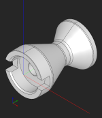
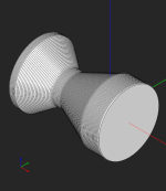
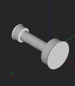
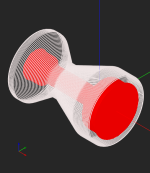
How can I extract turn profile from solid model?

Yoel

Looking around for some CAD
Hi, I'm new to occ and i saw your article "Build a swept volume for a turned part" on medium, it seems like can help me to solve the problem, but the article seems too brief, if I want to implement this by occ from scratch, what should I do from step to step? looking forward to you reply!
 
Last edited:

Quaoar

Administrator
Staff member
Hey @Yoel,

It's a little hard to answer your question as the MTS algorithm has never been open-sourced (at least not yet) by us, and I cannot give you the source code, which would apparently be the best way to answer. The blog post you mentioned refers to the paper by M. Watkins, which is essentially what we implemented as our "MTS1" algorithm. Later on, we evolved it into "MTS2," which allowed us to preserve feature edges of a model, but that's another story (I mention it here for completeness only).

The principle is quite simple, though. To put it briefly:

1. Convert the CAD part into a mesh with all mesh links preserved explicitly.
2. Project the mesh onto the turning axis (assuming you already know it).
3. Discretize the axis with a prescribed number of bins. In the simplest setting, you can use just a uniform distribution of bins. To be more intelligent, it's better to project all part's vertices to obtain a non-uniform bin distribution.
4. For each bin, intersect the corresponding plane with mesh links. The math for it is presented in the paper by Watkins.
5. For each bin, take the most distant intersection point and memorize it.
6. Connect all found points into a polyline. This is your swept profile.

If you tell me how far you got with the algorithm, I can probably be more specific.
 

Yoel

Looking around for some CAD
Hi @Quaoar,

Thank you for your careful and patient explanation. However, following the method you described, it appears that I can only obtain the outermost turn profile. Additionally, there seems to be an issue retrieving details inside the solid model, whether they deserve to be saved or not.

I have followed the method mentioned in the paper "Finding the maximum turnable state for mill/turn parts" to obtain the Maximum Turnable State (MTS):

1. Initially, I obtained the section curve from the solid model along the rotation axis at a certain step size using BRepAlgoAPI_Section in OCC. However, this process seemed too slow in some sections.

2. I then analyzed every loop in this section to determine its contribution to the final turn profile. This included identifying whether the loop is external (around material) or internal (not around material) and calculating the maximum and minimum distances of each loop to the rotation axis, as described in the mentioned paper. Through this method, I obtained some valid edges.

3. Subsequently, I constructed a rectangle face from each edge(the edge is perpendicular to the axis of rotation) and the step size.

4. My final objective is to aggregate all the faces to extract the curve of the boundary, which is what I need.

However, I encountered some problems during this process:

1. Initially, using BRepAlgoAPI_Section in OCC to obtain the curve seemed too slow in some sections.

2. Secondly, when discretizing the curve of the loop in each section into points, determining whether the closed curve is around the rotation axis, and calculating the maximum and minimum values of this loop, it appeared to lose some precision. Moreover, the calculation speed was too slow on some closed curves.

3. Lastly, if I were to create the final surface by aggregating many rectangular faces (the aggregation process has not been implemented yet) (I attempted to aggregate these TopoDS_Face using TopoDS_Compound and BRepBuilderAPI_Sewing, but the resulting TopoDS_Shape is not a TopoDS_Face. Moreover, in the synthesized TopoDS_Shape, the edges of the rectangles are retained, whereas I actually only need the outermost contour) , there was a noticeable jaggedness on some of the hypotenuses and curved edges.

I appreciate any insights or suggestions you may have regarding these challenges :)

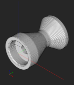
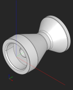
I have currently obtained results as shown in the following figure:
1705668860226.jpeg
 
Last edited:

Quaoar

Administrator
Staff member
@Yoel You're right; I forgot to mention that this whole approach does not take into account any lathed bores. Therefore, to make it work, there is another trick: build MTS separately for the exterior of the part, then apply it to the interior features.

For example, here is the initial lathed+milled part:

1705862408824.png

We build MTS for the turned faces:

1705862462847.png

As you can see, it's quite layered, but this situation can be improved by simplifying the rotated contour (we do not do that in MTS1).

Here is the MTS for bores:

1705862538707.png

Now we need to subtract one solid from another:

1705862584597.png

And this is how we obtain the final MTS:

1705862626953.png

I can say that this algorithm is pretty fast; we use it in instant pricing logic. Did you try to check your code with some decent profiler to see where hotspots come from?
 

Quaoar

Administrator
Staff member
BTW, the MTS2 algorithm (the improved version of MTS that was developed by @Andrey) gives a much cleaner shape:

1705862955640.png

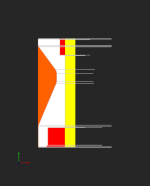
This is how we kind of "defeature" the milling features of a part and analyze turned volumes (red cells for steps, orange for grooves, yellow for central holes):

1705863113897.png

It took quite a while to develop this solution, so be ready to spend quite a bit of time.
 

Yoel

Looking around for some CAD
@Quaoar
Once again, thank you for your detailed and insightful response. Your answer has inspired me greatly, but there are some details I'm still unclear about.

1. How should I differentiate between the exterior and interior features of the solid model? While it's easy to distinguish the inner and outer surfaces of a solid model visually, I'm confused about how to achieve this through code.

2. As mentioned in your response, for example, if a contour obtained from a slice has multiple grooves, this cannot be achieved in your MTS1, but it can be obtained in MTS2?
 

Quaoar

Administrator
Staff member
@Yoel

Indeed, I should have mentioned that this approach to separating turned MTS from bored MTS requires preliminary feature recognition.

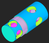
1706172229776.png

The recognition is done in several stages:

1. Recognize modeled threads and drilled holes.

2. Label faces that possess rotational symmetry. Here, we identify all candidate faces, i.e., those that can result from rotating a hypothetical generatrix around an axis. So far, we do not conclude on the final type of part (whether it is a turned part or not), but just label the candidate faces with the corresponding AAG attributes. The axes are stored as a tuple of direction and origin points.

3. Label planar faces whose axis is not fixed at any origin. For a planar face, we check its neighbors to know if it is a bore face or a turned face.

4. Using the set of labeled faces, extract the common turning axis. All labeled faces "vote" for an axis. The most "voted for" axis is selected as the main turning axis, so we employ a bit of democracy here.

5. Knowing the axis, we go for some more checks: override holes as bores if possible; check if modeled threads are coaxial with the main turning axis.

To decide if a face is internal or external, we have a bunch of methods like this:

Code:
bool RecognizeLathe::isInternal(const int     fid,
                                const double  diameter,
                                const double  u,
                                const double  v,
                                const gp_Ax1& ax) const
{
  const TopoDS_Face& face = m_aag->GetFace(fid);

  BRepAdaptor_Surface bas(face);
  BRepLProp_SLProps lprops( bas, u, v, 1, Precision::Confusion() );
  //
  if ( !lprops.IsNormalDefined() )
    return false;

  const gp_Pnt& cylPt   = lprops.Value();
  gp_Dir        cylNorm = lprops.Normal();
  //
  if ( face.Orientation() == TopAbs_REVERSED )
    cylNorm.Reverse();

  // Take a probe point along the normal.
  gp_Pnt normProbe = cylPt.XYZ() + cylNorm.XYZ()*diameter*0.05;

  // Compute the distance to the axis.
  gp_Lin axisLin(ax);
  //
  const double probeDist = axisLin.Distance(normProbe);
  const double cylDist   = axisLin.Distance(cylPt);
  //
  if ( probeDist < cylDist )
  {
    return true;
  }

  return false;
}

It is to check how the distance to a point changes if we shift a probe point along the candidate surface's normal.
 
Last edited:

Yoel

Looking around for some CAD
@Quaoar

Oh, my goodness, thank you so much, you're really great and so friendly, I appreciate your help very much. Wishing you good health and a happy life!!
 
Top