Topologize mesh
Overview
A typical reverse engineering scenario consists of the following main steps:
- Digitization.
- Segmentation.
- Surface reconstruction.
- Beautification.
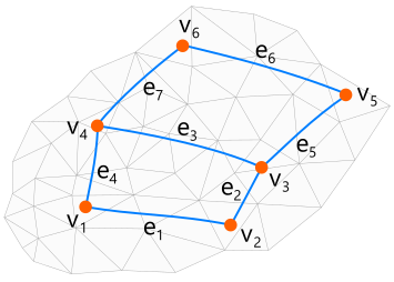
Interactive segmentation gives the user all means to outline the feature lines of the model manually. Given the mesh model as the input data, the user draws a network of curves which compose loops defining the patches. The wireframe model defines the layout of the surfaces (topology).
You can read more about our take on reverse engineering methods in the corresponding technical report [Slyadnev, 2019].
Internally, the wireframe model is defined as a directed hierarchical graph. The root elements in this graph are the patches. A patch contains an ordered list of coedges which are the lightweighted entries of edges plus "same sense" flags which allow to agree or disagree with the as-constructed orientation of an edge. The coedge-based wireframe structure allows for non-manifold surface modeling which can sometimes be useful.
In our reverse engineering workflow, the wireframe model is the master model. Manipulating wireframe patches is easy because you only need to modify edges, and the surface patches will be adjusted correspondingly. Another simplification of this wireframe approach is the lack of p-curves. As a result, there is no need to synchronize different curve representations to keep the model consistent. As a downside, such a representation scheme is not directly suitable for data interoperability as it is not fully compliant with, for example, STEP standard. To solve the interoperability issue and also to enable further modeling operations, the reverse engineering model is eventually converted to B-Rep scheme of OpenCascade.
Define contour interactively
Contour lines are defined interactively via re-define-contour command. Analysis Situs projects the straight line segments between the picked points onto mesh. Projection is performed with a certain precision which defines the max allowed distance between the subsequent points. Projection is performed non-recursively (to avoid stack overflows) with a controlled number of iterations. To speed up computations, BVH (bounding volume hierarchy) structure is used.

Anatomy of joint edge
For the sake of the local control over the reverse engineered patches, we have implemented an utility class named "joint adaptor." The purpose of this tool is to analyze the local topological situation near the given edge and provide all means to modify the corresponding piece of curve network and the surface patches filling the corresponding rectangular cells.
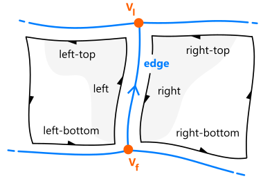
The Joint Adaptor accepts a single edge as an input and extracts its neighboring topological elements. In the figure above, the edge is shown in blue color. The arrow on the edge denotes the geometric (natural) orientation of the edge, i.e., the direction on its host curve determined by its inherent parameterization. The coedge which is agreed with the natural orientation of the primary edge is named "left." The opposite coedge is named "right." The same naming rule applies to the corresponding patches.