Wrong Geom_BSplineCurve (NURBS Curve) when returning from OCAF

Lingkan

CAD practitioner
Hi,

I'm trying to build a Geom_BSplineCurve from given NURBS Curve parameters, which look like the following:
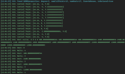
debug-info.png

When passing these parameters to the Geom_BSplineCurve API like:
C++:
Handle(Geom_BSplineCurve) curve =
    new Geom_BSplineCurve(poles, weights, knots, mults, degree,
                          Standard_False, isRational);

TopoDS_Edge edge = BRepBuilderAPI_MakeEdge(curve);

if (curve->IsClosed()) {
    return BRepBuilderAPI_MakeWire(edge);
}
return edge;

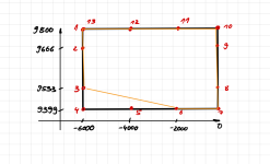
I get the following:
1670585323601.png
sketch.png
where the inner contour (yellow) is the created Geom_BSplineCurve, and the outer contour (black) is the desired output (Geom_BSplineCurve should look like this)

Any ideas on what the reason for this behavior is are much appreciated!
 

Quaoar

Administrator
Staff member
Can you please post here the poles, knots and multiplicities as text so that we can easily copy them to reproduce the issue?
 

Lingkan

CAD practitioner
Like this:

Code:
NURBSproperties: degree=3, numCtrlPoints=13, numKnots=17, form=Unknown, isRational=true

Control Point 1: [64.64, -6, 9.8], Weight: 1
Control Point 2: [64.64, -6, 9.666666666666666], Weight: 1
Control Point 3: [64.64, -6, 9.53333333333333], Weight: 1
Control Point 4: [64.64, -6, 9.399999999999997], Weight: 1
Control Point 5: [64.64, -4, 9.399999999999997], Weight: 1
Control Point 6: [64.64, -2, 9.399999999999997], Weight: 1
Control Point 7: [64.64, 0, 9.399999999999999], Weight: 1
Control Point 8: [64.64, 0, 9.533333333333331], Weight: 1
Control Point 9: [64.64, 0, 9.666666666666666], Weight: 1
Control Point 10: [64.64, 0, 9.8], Weight: 1
Control Point 11: [64.64, -2.0000000000000004, 9.8], Weight: 1
Control Point 12: [64.64, -4, 9.8], Weight: 1
Control Point 13: [64.64, -6, 9.8], Weight: 1

Knot vector: [0, 0, 0, 0, 400.00000000000364, 400.00000000000364, 400.00000000000364, 6400.0000000000036, 6400.00
00000000036, 6400.0000000000036, 6800.0000000000055, 6800.0000000000055, 6800.0000000000055, 12800.000000000005, 12800.0000000
00005, 12800.000000000005, 12800.000000000005]

Knot: 0
Mults: 4
Knot: 400.00000000000364
Mults: 3
Knot: 6400.000000000004
Mults: 3
Knot: 6800.0000000000055
Mults: 3
Knot: 12800.000000000005
Mults: 4
 

Quaoar

Administrator
Staff member
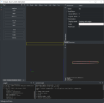
Looks fine to me:

1670596299160.png

With this code:

Code:
//-----------------------------------------------------------------------------

int MISC_Test(const Handle(asiTcl_Interp)& interp,
              int                          cmdMisc_NotUsed(argc),
              const char**                 argv)
{
  int degree=3;

  TColgp_Array1OfPnt Poles(1,13);
  TColStd_Array1OfReal Knots(1, 5);
  TColStd_Array1OfInteger Mults(1, 5);

  Poles(1) = gp_Pnt(64.64, -6, 9.8);
  Poles(2) = gp_Pnt(64.64, -6, 9.666666666666666);
  Poles(3) = gp_Pnt(64.64, -6, 9.53333333333333);
  Poles(4) = gp_Pnt(64.64, -6, 9.399999999999997);
  Poles(5) = gp_Pnt(64.64, -4, 9.399999999999997);
  Poles(6) = gp_Pnt(64.64, -2, 9.399999999999997);
  Poles(7) = gp_Pnt(64.64, 0, 9.399999999999999);
  Poles(8) = gp_Pnt(64.64, 0, 9.533333333333331);
  Poles(9) = gp_Pnt(64.64, 0, 9.666666666666666);
  Poles(10) = gp_Pnt(64.64, 0, 9.8);
  Poles(11) = gp_Pnt(64.64, -2.0000000000000004, 9.8);
  Poles(12) = gp_Pnt(64.64, -4, 9.8);
  Poles(13) = gp_Pnt(64.64, -6, 9.8);

  Knots(1) = 0;
  Knots(2) = 400.00;
  Knots(3) = 6400.00;
  Knots(4) = 6800.00;
  Knots(5) = 12800.00;

  Mults(1) = 4;
  Mults(2) = 3;
  Mults(3) = 3;
  Mults(4) = 3;
  Mults(5) = 4;

    Handle(Geom_BSplineCurve) curve =
      new Geom_BSplineCurve(Poles, Knots, Mults, degree,
                            Standard_False);

  interp->GetPlotter().REDRAW_CURVE("bcurve", curve, Color_White, true);

  TopoDS_Shape res = BRepBuilderAPI_MakeEdge(curve);

  if (curve->IsClosed()) {
      res = BRepBuilderAPI_MakeWire(TopoDS::Edge(res));
  }

  interp->GetPlotter().REDRAW_SHAPE("res", res);

  return TCL_OK;
}
 

Lingkan

CAD practitioner
Looks fine to me:

View attachment 476

With this code:

Code:
//-----------------------------------------------------------------------------

int MISC_Test(const Handle(asiTcl_Interp)& interp,
              int                          cmdMisc_NotUsed(argc),
              const char**                 argv)
{
  int degree=3;

  TColgp_Array1OfPnt Poles(1,13);
  TColStd_Array1OfReal Knots(1, 5);
  TColStd_Array1OfInteger Mults(1, 5);

  Poles(1) = gp_Pnt(64.64, -6, 9.8);
  Poles(2) = gp_Pnt(64.64, -6, 9.666666666666666);
  Poles(3) = gp_Pnt(64.64, -6, 9.53333333333333);
  Poles(4) = gp_Pnt(64.64, -6, 9.399999999999997);
  Poles(5) = gp_Pnt(64.64, -4, 9.399999999999997);
  Poles(6) = gp_Pnt(64.64, -2, 9.399999999999997);
  Poles(7) = gp_Pnt(64.64, 0, 9.399999999999999);
  Poles(8) = gp_Pnt(64.64, 0, 9.533333333333331);
  Poles(9) = gp_Pnt(64.64, 0, 9.666666666666666);
  Poles(10) = gp_Pnt(64.64, 0, 9.8);
  Poles(11) = gp_Pnt(64.64, -2.0000000000000004, 9.8);
  Poles(12) = gp_Pnt(64.64, -4, 9.8);
  Poles(13) = gp_Pnt(64.64, -6, 9.8);

  Knots(1) = 0;
  Knots(2) = 400.00;
  Knots(3) = 6400.00;
  Knots(4) = 6800.00;
  Knots(5) = 12800.00;

  Mults(1) = 4;
  Mults(2) = 3;
  Mults(3) = 3;
  Mults(4) = 3;
  Mults(5) = 4;

    Handle(Geom_BSplineCurve) curve =
      new Geom_BSplineCurve(Poles, Knots, Mults, degree,
                            Standard_False);

  interp->GetPlotter().REDRAW_CURVE("bcurve", curve, Color_White, true);

  TopoDS_Shape res = BRepBuilderAPI_MakeEdge(curve);

  if (curve->IsClosed()) {
      res = BRepBuilderAPI_MakeWire(TopoDS::Edge(res));
  }

  interp->GetPlotter().REDRAW_SHAPE("res", res);

  return TCL_OK;
}
I can confirm this works as it is supposed to. If I export directly after it's created, the resulting curve is as it's supposed to be (test.stp).

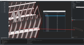
It somehow gets messed up when building/appending it to the assembly structure... which looks like this:1670600680872.png

The assembly structure is done like so:
C++:
// outer-contour-prototype.cc
TopoDS_Shape ReadOuterContour(...) {
    TopoDS_Shape curveShape = ReadCurve(...); // like in the code above
    // null checks...

    // Add Contour node in OCAF
    TDF_Label contourLabel = ...->OCAFShapeTool()->AddShape(curveShape, false);
    TDataStd_Name::Set(contourLabel, "Contour");
    ...->OCAFColorTool()->SetColor(contourLabel, someColor, XCAFDoc_ColorCurv);

    return TopoDS::Wire(curveShape);
}

// outer-contour-parent-prototype.cc
std::list<TopoDS_Shape> shapes;

TopoDS_Shape ReadParent(...) {
    TopoDS_Shape outerContour = ReadOuterContour(...);
    // null checks...
    shapes.push_back(outerContour);
   
    // other shapes e.g. ComposedOf
    shapes.push_back(otherShape);
   
    // make assembly from shapes
    TopoDS_Compound assy;
    BRep_Builder builder;
    builder.MakeCompound(assy);
    for (TopoDS_Shape const &shape : shapes) {
        builder.Add(assy, shape);
    }

    TDF_Label assyLabel = ...->OCAFShapeTool()->AddShape(assy, true);
    TDataStd_Name::Set(assyLabel, "Assembly");

    return assy;
}
 

Attachments

  • test.stp
    2.7 KB · Views: 1

Quaoar

Administrator
Staff member
Interesting. Are you somehow extending CAD Assistant? I wonder, if you can export your document to an xbf file so that I can try opening it in Draw.
 

Lingkan

CAD practitioner

Lingkan

CAD practitioner
Interesting. Are you somehow extending CAD Assistant? I wonder, if you can export your document to an xbf file so that I can try opening it in Draw.
It seems like a cannot upload xml or xbf file format to this forum. So I'll provide it via google drive instead: link
 

Quaoar

Administrator
Staff member
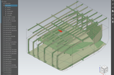
I'm not sure if I'm navigating through the document's contents correctly, but I can see some closed splines there:

1671186461193.png
 
Top