You are using an out of date browser. It may not display this or other websites correctly.
You should upgrade or use an alternative browser.
You should upgrade or use an alternative browser.
Seam removal
- Thread starter Daimir
- Start date
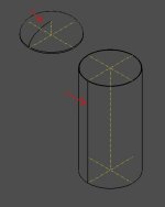
Those seam edges are the essential part of a face representation in OpenCascade. For any periodic surfaces, they go through the period value to close the parametric UV domain of a surface (otherwise it would remain unclosed). What you probably want to ask is how to get rid of those edges visually (as they might seem useless from engineering perspective), but that is what your visualization subsystem is responsible for (not OpenCascade as a kernel). You may want to precise what exactly you mean and which tools you're using to continue conversation.
Also, make sure to post in English, otherwise nobody will respond")
Also, make sure to post in English, otherwise nobody will respond
Last edited:
Hello. "What you probably want to ask is how to get rid of those edges visually (as they might seem useless from engineering perspective)" - Yes, that's right!
my code:
void Cylindrical_ShellElement::ComputeElement()
{
Standard_Real Dw = myCylParams.Dw; //diameter
Standard_Real hcil = myCylParams.hcil; //height
Standard_Real s = myCylParams.s; //thickness
gp_Pnt PntLoc, Pnt1, Pnt2, Pnt3, Pnt4;
PntLoc.SetCoord(0, 0, 0);
Pnt1.SetCoord(Dw / 2, 0, 0);
Pnt2.SetCoord(Dw / 2 + s, 0, 0);
Pnt3.SetCoord(Dw / 2 + s, 0, hcil);
Pnt4.SetCoord(Dw / 2, 0, hcil);
gp_Dir N;
gp_Dir Vx;
N.SetCoord(0, 1, 0);
Vx.SetCoord(1, 0, 0);
gp_Ax2 A2(PntLoc, N, Vx);
Handle(Geom_TrimmedCurve) aSegment1 = GC_MakeSegment(Pnt1, Pnt2);
Handle(Geom_TrimmedCurve) aSegment2 = GC_MakeSegment(Pnt2, Pnt3);
Handle(Geom_TrimmedCurve) aSegment3 = GC_MakeSegment(Pnt3, Pnt4);
Handle(Geom_TrimmedCurve) aSegment4 = GC_MakeSegment(Pnt4, Pnt1);
TopoDS_Edge anEdge1 = BRepBuilderAPI_MakeEdge(aSegment1);
TopoDS_Edge anEdge2 = BRepBuilderAPI_MakeEdge(aSegment2);
TopoDS_Edge anEdge3 = BRepBuilderAPI_MakeEdge(aSegment3);
TopoDS_Edge anEdge4 = BRepBuilderAPI_MakeEdge(aSegment4);
BRepBuilderAPI_MakeWire Wc = BRepBuilderAPI_MakeWire();
Wc.Add(anEdge1);
Wc.Add(anEdge2);
Wc.Add(anEdge3);
Wc.Add(anEdge4);
TopoDS_Wire Wire = BRepBuilderAPI_MakeWire(Wc).Wire();
TopoDS_Face F = BRepBuilderAPI_MakeFace(Wire);
gp_Ax1 axe = gp_Ax1(gp_Pnt(0., 0., 0.), gp_Dir(0., 0., 1.0));
Standard_Real FullAngle = 2.00000000*M_PI;
TopoDS_Shape full_Shape = BRepPrimAPI_MakeRevol(F, axe, FullAngle);
Set_fShape(full_Shape);
}
How can I remove these seams from the outline? thanks
Hello Daimir,Hello. "What you probably want to ask is how to get rid of those edges visually (as they might seem useless from engineering perspective)" - Yes, that's right!
my code:
void Cylindrical_ShellElement::ComputeElement()
{
Standard_Real Dw = myCylParams.Dw; //diameter
Standard_Real hcil = myCylParams.hcil; //height
Standard_Real s = myCylParams.s; //thickness
gp_Pnt PntLoc, Pnt1, Pnt2, Pnt3, Pnt4;
PntLoc.SetCoord(0, 0, 0);
Pnt1.SetCoord(Dw / 2, 0, 0);
Pnt2.SetCoord(Dw / 2 + s, 0, 0);
Pnt3.SetCoord(Dw / 2 + s, 0, hcil);
Pnt4.SetCoord(Dw / 2, 0, hcil);
gp_Dir N;
gp_Dir Vx;
N.SetCoord(0, 1, 0);
Vx.SetCoord(1, 0, 0);
gp_Ax2 A2(PntLoc, N, Vx);
Handle(Geom_TrimmedCurve) aSegment1 = GC_MakeSegment(Pnt1, Pnt2);
Handle(Geom_TrimmedCurve) aSegment2 = GC_MakeSegment(Pnt2, Pnt3);
Handle(Geom_TrimmedCurve) aSegment3 = GC_MakeSegment(Pnt3, Pnt4);
Handle(Geom_TrimmedCurve) aSegment4 = GC_MakeSegment(Pnt4, Pnt1);
TopoDS_Edge anEdge1 = BRepBuilderAPI_MakeEdge(aSegment1);
TopoDS_Edge anEdge2 = BRepBuilderAPI_MakeEdge(aSegment2);
TopoDS_Edge anEdge3 = BRepBuilderAPI_MakeEdge(aSegment3);
TopoDS_Edge anEdge4 = BRepBuilderAPI_MakeEdge(aSegment4);
BRepBuilderAPI_MakeWire Wc = BRepBuilderAPI_MakeWire();
Wc.Add(anEdge1);
Wc.Add(anEdge2);
Wc.Add(anEdge3);
Wc.Add(anEdge4);
TopoDS_Wire Wire = BRepBuilderAPI_MakeWire(Wc).Wire();
TopoDS_Face F = BRepBuilderAPI_MakeFace(Wire);
gp_Ax1 axe = gp_Ax1(gp_Pnt(0., 0., 0.), gp_Dir(0., 0., 1.0));
Standard_Real FullAngle = 2.00000000*M_PI;
TopoDS_Shape full_Shape = BRepPrimAPI_MakeRevol(F, axe, FullAngle);
Set_fShape(full_Shape);
}
How can I remove these seams from the outline? thanks
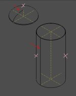
You provided the code which creates geometric primitives. As Sergey explained the seam edges are mandatory entity and cannot be avoided at this level. What you can do to cope with seam edges visually is to enhance the logic responsible for creation of graphics primitives for the given geometry. So that, please, post here the code you use to display the geometry in 3D viewer.
I can't provide all the program code. here is the setting code
void OCCObject::OCCObject(System::Windows::Forms::Control^ control, const Handle(Graphic3d_GraphicDriver)& GraphicDriver,
const V3d_TypeOfOrientation theOrientation,
const Graphic3d_TypeOfShadingModel theType = Graphic3d_TOSM_NONE)
{
try {
myViewer = new V3d_Viewer(GraphicDriver);
//! масштаб изображения. По умолчанию 1:2000
myViewer->SetDefaultViewSize(2000.0);
//! ориентация пространства
myViewer->SetDefaultViewProj(theOrientation);
//! цвет фона
myViewer->SetDefaultBackgroundColor(Quantity_NOC_GRAY30);
//! V3d_WIREFRAME - каркасный режим, V3d_ZBUFFER - режим затенения
myViewer->SetDefaultVisualization(V3d_ZBUFFER);
//! Graphic3d_TOSM_NONE - как чертеж, закраска граней сливается с цветом фона
//! Graphic3d_TOSM_VERTEX - 3D изображение
myViewer->SetDefaultShadingModel(theType);
//! устанавливает режим вычисления скрытых линий. Не работает
myViewer->SetComputedMode(Standard_False);
//! устанавливает режим вычисления скрытых линий по умолчанию. Не работает
myViewer->SetDefaultComputedMode(Standard_False);
//! Определяет источники света по умолчанию. См. справку Open Cascade
myViewer->SetDefaultLights();
//! Активирует все источники света, определенные в этом средстве просмотра
myViewer->SetLightOn();
//! создаются новые пользовательские слои
myViewer->AddZLayer(int_ZlayerID_solids);
myViewer->AddZLayer(int_ZlayerID_geom);
Graphic3d_ZLayerSettings obj_Zsettings_11 = myViewer->ZLayerSettings(int_ZlayerID_solids);
Graphic3d_ZLayerSettings obj_Zsettings_12 = myViewer->ZLayerSettings(int_ZlayerID_geom);
//! Устанавливает минимально возможное отрицательное смещение глубины
//! Закрашивается перекрытие объектов
obj_Zsettings_11.SetDepthOffsetNegative();
//! Устанавливает минимально возможное положительное смещение глубины
//! Видно над всеми объектами
obj_Zsettings_12.SetDepthOffsetPositive();
myViewer->SetZLayerSettings(int_ZlayerID_solids, obj_Zsettings_11);
myViewer->SetZLayerSettings(int_ZlayerID_geom, obj_Zsettings_12);
myAISContext = new AIS_InteractiveContext(myViewer);
myAISContext->SetDisplayMode(AIS_Shaded, false);
myView = myViewer->CreateView();
const Handle(Prs3d_Drawer) drawer = myAISContext->DefaultDrawer();
//! Устанавливаются параметры отображения контура (линия - толщина 1, цвет черный, сплошная)
drawer->SetFaceBoundaryDraw(Standard_True);
drawer->FaceBoundaryAspect()->SetWidth(1);
drawer->FaceBoundaryAspect()->SetColor(Quantity_NOC_BLACK);
drawer->FaceBoundaryAspect()->SetTypeOfLine(Aspect_TOL_SOLID);
//! Устанавливаются параметры отображения граней (цвет - сливается с фоном,
//! цвет линии контура - черный, толщина - 3, сплошная). Не работает. Перебивается
//! в классе AIS_DrawShape
const Handle(Prs3d_ShadingAspect)& shadingAspect = drawer->ShadingAspect();
shadingAspect->SetColor(Quantity_NOC_GRAY30);
drawer->SetFreeBoundaryDraw(Standard_True);
drawer->FreeBoundaryAspect()->SetWidth(3);
drawer->FreeBoundaryAspect()->SetColor(Quantity_NOC_BLACK);
drawer->FreeBoundaryAspect()->SetTypeOfLine(Aspect_TOL_SOLID);
HWND winHWND = (HWND)control->Handle.ToPointer();
Handle(WNT_Window) aWNTWindow = new WNT_Window(winHWND);
myView->SetWindow(aWNTWindow);
if (!aWNTWindow->IsMapped()) aWNTWindow->Map();
//! отключается режим вычисления скрытых линий
myView->SetComputedMode(false);
//! включается режим автоматической подсветки при обнаружении мышкой
myAISContext->SetAutomaticHilight(true);
}
catch (Standard_Failure)
{
MessageBox::Show(L"Error Ocured in Initializing the Opencascade graphic variable");
}
};
onwards in the program the objects are displayed by Handle(AIS_InteractiveContext) myAISContext->Display(AIS_Obj, Standard_False);
I guess, i changed AIS_Shape to calculate outlines, maybe this is the consequence
You should inherit AIS_Shape and update its Compute method with the logic you need, namely, avoid graphics primitives creation fo seam edges. And then use this customized AIS_Shape instead of standard one in the code responsible for scene initialization.I can't provide all the program code. here is the setting code
void OCCObject::OCCObject(System::Windows::Forms::Control^ control, const Handle(Graphic3d_GraphicDriver)& GraphicDriver,
const V3d_TypeOfOrientation theOrientation,
const Graphic3d_TypeOfShadingModel theType = Graphic3d_TOSM_NONE)
{
try {
myViewer = new V3d_Viewer(GraphicDriver);
//! масштаб изображения. По умолчанию 1:2000
myViewer->SetDefaultViewSize(2000.0);
//! ориентация пространства
myViewer->SetDefaultViewProj(theOrientation);
//! цвет фона
myViewer->SetDefaultBackgroundColor(Quantity_NOC_GRAY30);
//! V3d_WIREFRAME - каркасный режим, V3d_ZBUFFER - режим затенения
myViewer->SetDefaultVisualization(V3d_ZBUFFER);
//! Graphic3d_TOSM_NONE - как чертеж, закраска граней сливается с цветом фона
//! Graphic3d_TOSM_VERTEX - 3D изображение
myViewer->SetDefaultShadingModel(theType);
//! устанавливает режим вычисления скрытых линий. Не работает
myViewer->SetComputedMode(Standard_False);
//! устанавливает режим вычисления скрытых линий по умолчанию. Не работает
myViewer->SetDefaultComputedMode(Standard_False);
//! Определяет источники света по умолчанию. См. справку Open Cascade
myViewer->SetDefaultLights();
//! Активирует все источники света, определенные в этом средстве просмотра
myViewer->SetLightOn();
//! создаются новые пользовательские слои
myViewer->AddZLayer(int_ZlayerID_solids);
myViewer->AddZLayer(int_ZlayerID_geom);
Graphic3d_ZLayerSettings obj_Zsettings_11 = myViewer->ZLayerSettings(int_ZlayerID_solids);
Graphic3d_ZLayerSettings obj_Zsettings_12 = myViewer->ZLayerSettings(int_ZlayerID_geom);
//! Устанавливает минимально возможное отрицательное смещение глубины
//! Закрашивается перекрытие объектов
obj_Zsettings_11.SetDepthOffsetNegative();
//! Устанавливает минимально возможное положительное смещение глубины
//! Видно над всеми объектами
obj_Zsettings_12.SetDepthOffsetPositive();
myViewer->SetZLayerSettings(int_ZlayerID_solids, obj_Zsettings_11);
myViewer->SetZLayerSettings(int_ZlayerID_geom, obj_Zsettings_12);
myAISContext = new AIS_InteractiveContext(myViewer);
myAISContext->SetDisplayMode(AIS_Shaded, false);
myView = myViewer->CreateView();
const Handle(Prs3d_Drawer) drawer = myAISContext->DefaultDrawer();
//! Устанавливаются параметры отображения контура (линия - толщина 1, цвет черный, сплошная)
drawer->SetFaceBoundaryDraw(Standard_True);
drawer->FaceBoundaryAspect()->SetWidth(1);
drawer->FaceBoundaryAspect()->SetColor(Quantity_NOC_BLACK);
drawer->FaceBoundaryAspect()->SetTypeOfLine(Aspect_TOL_SOLID);
//! Устанавливаются параметры отображения граней (цвет - сливается с фоном,
//! цвет линии контура - черный, толщина - 3, сплошная). Не работает. Перебивается
//! в классе AIS_DrawShape
const Handle(Prs3d_ShadingAspect)& shadingAspect = drawer->ShadingAspect();
shadingAspect->SetColor(Quantity_NOC_GRAY30);
drawer->SetFreeBoundaryDraw(Standard_True);
drawer->FreeBoundaryAspect()->SetWidth(3);
drawer->FreeBoundaryAspect()->SetColor(Quantity_NOC_BLACK);
drawer->FreeBoundaryAspect()->SetTypeOfLine(Aspect_TOL_SOLID);
HWND winHWND = (HWND)control->Handle.ToPointer();
Handle(WNT_Window) aWNTWindow = new WNT_Window(winHWND);
myView->SetWindow(aWNTWindow);
if (!aWNTWindow->IsMapped()) aWNTWindow->Map();
//! отключается режим вычисления скрытых линий
myView->SetComputedMode(false);
//! включается режим автоматической подсветки при обнаружении мышкой
myAISContext->SetAutomaticHilight(true);
}
catch (Standard_Failure)
{
MessageBox::Show(L"Error Ocured in Initializing the Opencascade graphic variable");
}
};
onwards in the program the objects are displayed by Handle(AIS_InteractiveContext) myAISContext->Display(AIS_Obj, Standard_False);
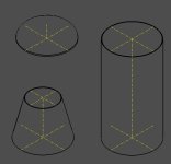
I succeeded, inherited AIS_Shape and updated its Compute method
I found all edges whithout seams so:
TopoDS_Shape Edges;
BRep_Builder B;
B.MakeCompound(TopoDS::Compound(Edges));
TopExp_Explorer Ex(myshape, TopAbs_FACE);
while (Ex.More())
{
const TopoDS_Face& face = TopoDS::Face(Ex.Current());
TopExp_Explorer ExW(face, TopAbs_WIRE);
while (ExW.More())
{
const TopoDS_Wire& wire = TopoDS::Wire(ExW.Current());
const Handle(ShapeExtend_WireData) wData = new ShapeExtend_WireData(wire);
Standard_Integer edcount = wData->NbEdges();
for (int ind = 1; ind <= edcount; ind++)
{
if (wData->IsSeam(ind)) continue;
const TopoDS_Edge& anEdge = wData->Edge(ind);
B.Add(Edges, anEdge);
}
ExW.Next();
}
Ex.Next();
}
Than i got polylines from Edges and changed primitives to new primitives aPrims:
Standard_Real aShapeDeflection = StdPrs_ToolTriangulatedShape::GetDeflection(myshape, myDrawer);
Prs3d_NListOfSequenceOfPnt thePolylines;
addEdges(Edges, myDrawer, aShapeDeflection, thePolylines);
Handle(Graphic3d_ArrayOfPrimitives) aPrims = Prs3d:rimitivesFromPolylines(thePolylines);
if (!aPrims.IsNull())
{
Handle(Graphic3d_AspectLine3d) aBoundaryAspect = myDrawer->FaceBoundaryAspect()->Aspect();
aBoundaryAspect->SetWidth(Standard_Real(2));
Handle(Graphic3d_Group) aPrsGrp = aPrs->CurrentGroup();
aPrsGrp->Clear();
aPrsGrp->SetGroupPrimitivesAspect(aBoundaryAspect);
aPrsGrp->AddPrimitiveArray(aPrims);
}
I found all edges whithout seams so:
TopoDS_Shape Edges;
BRep_Builder B;
B.MakeCompound(TopoDS::Compound(Edges));
TopExp_Explorer Ex(myshape, TopAbs_FACE);
while (Ex.More())
{
const TopoDS_Face& face = TopoDS::Face(Ex.Current());
TopExp_Explorer ExW(face, TopAbs_WIRE);
while (ExW.More())
{
const TopoDS_Wire& wire = TopoDS::Wire(ExW.Current());
const Handle(ShapeExtend_WireData) wData = new ShapeExtend_WireData(wire);
Standard_Integer edcount = wData->NbEdges();
for (int ind = 1; ind <= edcount; ind++)
{
if (wData->IsSeam(ind)) continue;
const TopoDS_Edge& anEdge = wData->Edge(ind);
B.Add(Edges, anEdge);
}
ExW.Next();
}
Ex.Next();
}
Than i got polylines from Edges and changed primitives to new primitives aPrims:
Standard_Real aShapeDeflection = StdPrs_ToolTriangulatedShape::GetDeflection(myshape, myDrawer);
Prs3d_NListOfSequenceOfPnt thePolylines;
addEdges(Edges, myDrawer, aShapeDeflection, thePolylines);
Handle(Graphic3d_ArrayOfPrimitives) aPrims = Prs3d:
rimitivesFromPolylines(thePolylines);if (!aPrims.IsNull())
{
Handle(Graphic3d_AspectLine3d) aBoundaryAspect = myDrawer->FaceBoundaryAspect()->Aspect();
aBoundaryAspect->SetWidth(Standard_Real(2));
Handle(Graphic3d_Group) aPrsGrp = aPrs->CurrentGroup();
aPrsGrp->Clear();
aPrsGrp->SetGroupPrimitivesAspect(aBoundaryAspect);
aPrsGrp->AddPrimitiveArray(aPrims);
}
Attachments
Last edited: