Extending a shell 25mm

edoelas

CAD practitioner
Hi everybody,
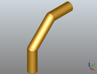
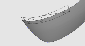
I just came across a problem I don't know how to solve (and believe me, I tried). I want to create an extension of an open shell, more or less something like this:
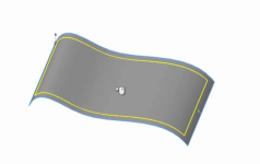
1654846249661.png
Imagine the yellow line is the original shape and the blue line is the extension. My plan was to, given a face, edge and distance generate an offset edge tangent to the face at the given distance. Then use a filling algorithm to fill the gap. I have tried different OCCT classes and none of them seems to allow me to create the offset edge how I want. Some like BRepOffset_MakeOffset allow me to create the offset edge but I don't have a way to make it tangent to the surface. I don't need it to be perfect, just good enough.

I hope I explained myself well enough, if not please let me know. Thanks!

EDIT: this approach is the one I thought would work the best, any different approach that solves the problem is welcome.
 

Quaoar

Administrator
Staff member
As a quick thought, if it is a single surface, then GeomLib::ExtendSurfByLength() could be of some use.
 

edoelas

CAD practitioner
As a quick thought, if it is a single surface, then GeomLib::ExtendSurfByLength() could be of some use.
I have been trying this but I need a Handle<Geom_BoundedSurface> and when I downcast the Handle<Geom_Surface> to get it returns null. This is the code I have tried:

C++:
Handle(Geom_Surface) geomSurf = BRep_Tool::Surface(face);
Handle(Geom_BoundedSurface) geomBoundSurf = Handle(Geom_BoundedSurface)::DownCast(geomSurf);
GeomLib::ExtendSurfByLength(geomBoundSurf, 25, 1, true, true);
auto faceBuilder = BRepBuilderAPI_MakeFace(geomBoundSurf, 1);

_assembly->AddShape(faceBuilder.Face());
 

edoelas

CAD practitioner
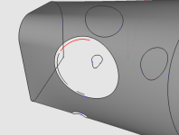
It happens with any step I try. This is one test I use, it just has one face. I don't care about the inner hole, I am just worried about an external extension. Also, this shape is flat, so I know I can compute the offset wire using BRepOffsetAPI_MakeOffset, but with more complex shapes it does not work as expected (the created wire is not tangent to the face).
 

Attachments

  • hex_hole.stp
    11.7 KB · Views: 3

Quaoar

Administrator
Staff member
1654863727141.png

To make this specific case (as well as any other with 1 surface) work, the missing stage is the conversion to spline:

Code:
TopoDS_Shape
      newShape = ShapeCustom::ConvertToBSpline(shape, true, true, true, true);
 

blobfish

CAD community veteran
I assume you can stay at the topology level. Considering the single face scenario, I dug into the defeaturing and it uses BRepLib::ExtendFace. I don't think occt has anything for extending a mult-face shell.
 

edoelas

CAD practitioner
Thanks Quaoar, that was the problem, I was not converting it to BSpline.

Blobfish, I have tried BRepLib::ExtendFace and it works the same but with fewer lines, so unless there is a hidden difference I will stick with this one. Thanks.

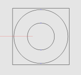
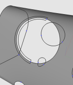
These suggestions solve half of my problem. Now I have an extension of a face, but the newly generated face is square. In this example I have extended 25mm each side:
1654870846499.png

Now I have to make sure that the extension is just 25bigger than the outer wire. I guess I have to trim the newly created face. Any suggestion about how to archive this?
 

Quaoar

Administrator
Staff member
So it all comes down to the necessity to offset the contour and retrim the face. What if you offset the outer wire in the UV space of a face? In 2D it should be easier (although the offset might be distorted because of the parameterization of the spline). Not sure if OpenCascade contains any tool for that. We were exprementing with 2D offsets in the team, but they were discrete (polylines).
 

edoelas

CAD practitioner
Yes, the problem is that I have found no tool that allows me to offset the wire in the UV space of the face.
A more wild approach that might also work is to create a circular pipe sweeping around the wire, then calculate the intersection between the pipe and the extended face. That should give me two offset wires, an inner and an outer one.
 

blobfish

CAD community veteran
Yes, the problem is that I have found no tool that allows me to offset the wire in the UV space of the face.
A more wild approach that might also work is to create a circular pipe sweeping around the wire, then calculate the intersection between the pipe and the extended face. That should give me two offset wires, an inner and an outer one.
I love it! Another crazy idea is to thicken the face into a solid and run that solid through an offset operation targeting the perimeter faces. Assuming that works you can extract the original face from the offset solid. I used to do this manually in Unigraphics years ago.
 

Quaoar

Administrator
Staff member
A more wild approach that might also work is to create a circular pipe sweeping around the wire, then calculate the intersection between the pipe and the extended face.
Love it! That reminds me of sweet days in OCC! "Let's build a pipe and this way get the offset." But it's not general, is it? Do you need a general solution or something that works for these specific cases only?
 

edoelas

CAD practitioner
That's a good question. I don't think it is. I don't think I will find a general solution for this problem without a Ph.D. in maths. But it does not have to be perfect, it just needs to be good enough, so if I can detect problematic cases and solve them, it should be fine. For this to work properly, I think the external wire should have G1 continuity, which should happen in most cases, but nobody guarantees me that the user will behave properly and load the proper shapes.

Another option is to use the "balls and cylinders technique":
1654874678607.png
This way I will have a smooth continuous offset, it does not matter if the wire is G1 continuous or not. The only problem is that this technique is a bit more involved and I should make a solid out of all the elements before checking the intersection. In my head this works properly, but I am sure opencascade disagrees.

Another crazy idea is to thicken the face into a solid and run that solid through an offset operation targeting the perimeter faces. Assuming that works you can extract the original face from the offset solid. I used to do this manually in Unigraphics years ago.
Using a face thickening operation as suggested by blobfish is another great idea, this way I don't have to create the pipe manually and the intersection will just result in the external wire instead of two wires.
 
Last edited:

edoelas

CAD practitioner
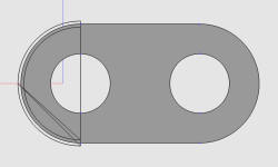
I have removed the unnecessary wires, but now I am facing a really weird problem I do not know how to solve. I am using BRepAlgoAPI_Section to check the intersection between the pipe and the face. Sometimes it works, but others it does not:
1655206669583.png
As you can see, instead of one continuous edge I am getting 3 edges with gaps. I have rendered the pipe and the surface and everything seems alright. I have no clue why this is happening. This is the code I am using, sorry if it is a bit messy. The input shapes are face and edge.

C++:
        TopoDS_Face extendedFace;
        BRepLib::ExtendFace(face, 25, true, true, true, true, extendedFace);

        ShapeAnalysis_Edge edgeA = ShapeAnalysis_Edge();
        gp_Pnt iniPt = BRep_Tool::Pnt(edgeA.FirstVertex(edge));

        Handle(Geom_Curve) curve;
        Standard_Real a, b;
        edgeA.Curve3d(edge, curve, a, b);
        gp_Pnt P;
        gp_Vec V1;
        curve->D1(0, P, V1);
     
        auto circle = gp_Circ(gp_Ax2(iniPt, V1), 25);
        auto profile_edge = BRepBuilderAPI_MakeEdge(circle).Edge();
        auto pipe = BRepOffsetAPI_MakePipe(BRepBuilderAPI_MakeWire(edge).Wire(), profile_edge).Shape();
        //auto profile_wire = BRepBuilderAPI_MakeWire(profile_edge).Wire();
        //auto profile_face = BRepBuilderAPI_MakeFace(profile_wire).Face();

        BRepAlgoAPI_Section intersection(pipe, extendedFace);
        auto dbg = intersection.Shape();
        for (TopExp_Explorer it(dbg, TopAbs_EDGE); it.More(); it.Next()) {
            auto checkEdge = TopoDS::Edge(it.Value());
            auto intersectionChecker = IntTools_EdgeFace();
            intersectionChecker.SetEdge(checkEdge);
            intersectionChecker.SetFace(face);
            intersectionChecker.Perform();
            if (intersectionChecker.CommonParts().IsEmpty()) {
                auto wireBuilder2 = BRepBuilderAPI_MakeWire();
                wireBuilder2.Add(checkEdge);
                _assembly->AddShape(wireBuilder2.Wire());
            }
        }

I am using an edge to create the pipe, so I was expecting to get one continuous edge for the inner offset and another one for the outer offset. The only thing that comes to my head is that BRepAlgoAPI_Section is not working properly. The step used in the image is attached.

Thanks!

UPDATE1:
I have tried to create the pipe with a square instead of with a circle. Maybe the problem is in the function that checks the intersection. It seems that with a square it works properly:
1655216972342.png
The problem is that since the face can rotate and the square will not, the distance of the offset might not be constant. As far as I know there is no way to make the square rotate with the surface. My crappy but good enough solution is to make a polygon with many sides, so the distance varies within a small range. For my use case, this is good enough, but I think it is far from a great solution.

UPDATE2:
It seems it was just a coincidence, testing on more files has shown the same problem as with the circle.
 

Attachments

  • test_vase.STP
    561.5 KB · Views: 4
Last edited:

Quaoar

Administrator
Staff member
Here's my result with your code. The inner offset is sort of broken, indeed. Also, the intersection was quite slow to compute.
 

Attachments

  • pipe.gif
    pipe.gif
    2 MB · Views: 6

Quaoar

Administrator
Staff member
What I noticed is that your pipe was reversed (all face norms were pointing inside the pipe). If you reverse your pipe tool, then it sort of helps:

1655291302326.png

I just tweaked your code like that:

Code:
auto circle = gp_Circ(gp_Ax2(iniPt, V1.Reversed()), 25);

It's likely a poor assumption that worked in this particular case though.
 

edoelas

CAD practitioner
Hi, I have tried reversing the circle, and sometimes helps, but all the time. What I have found out that seems to work is using BRepFill_Pipe with ForceApproxC1=true to create the pipe, but this has two problems:
  1. Even if it seems an improvement it still has issues with some shapes. I have attached one of these shapes.
  2. For some unknown reason, it launches an exception that I haven't solved with certain edges. I am trying to create a simplified shape to recreate the problem but I haven't been able to.
I will try GeomFill_Pipe but I am afraid that the outcome will be the same.

Also, now I am checking if the edge is reversed so the initial direction of the profile is fine with reversed wires. Now the code just before creating the gp_Circ looks like this:

Code:
gp_Pnt iniPt;
ShapeAnalysis_Edge edgeA = ShapeAnalysis_Edge();
if (edge.Orientation() == TopAbs_FORWARD)
iniPt = BRep_Tool::Pnt(edgeA.FirstVertex(edge));
else
iniPt = BRep_Tool::Pnt(edgeA.LastVertex(edge));

Handle(Geom_Curve) curve;
Standard_Real a, b;
edgeA.Curve3d(edge, curve, a, b);
gp_Pnt P;
gp_Vec V1;
curve->D1(0, P, V1);


About the problem in the corners: I will have to check that, but is not that big of a deal since the algorithm I am using to fill the gap between the face and the offset adds missing edges.

About what I need this for: Is in order to do some simulations. Those simulations are not 100% precise with position, so I have to extend the borders of the shapes to avoid artifacts.
 

Attachments

  • patata_2d.step
    8.1 KB · Views: 4
Top