Topology graph
Because of its inherent simplicity, the apparatus of graph theory found extensive use in industrial geometric modeling. One of the well-turned ideas emerged early on was distinguishing between the syntax (topology) and the semantics (geometry) of digital shape representation. In the boundary representation scheme, the topology can be expressed in the form of an acyclic directed simple graph (having no self-loops and parallel edges [Deo, 1974]). The topology graph determines how the primary topological elements (faces, edges, and vertices) are nested. The possibility to have several parent nodes for a single child enables sharing and instancing of the boundary elements.
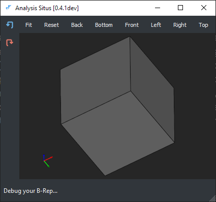
Let's take a simple box shape in its boundary representation.
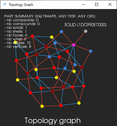
The topology graph is the B-rep structure itself, so to construct the explicit graph, one has to iterate from the topmost boundary elements (compounds, solids, etc.) down to the atomic entities, i.e., vertices while constructing the corresponding graph nodes and arcs along the way. The following image illustrates a formal topology graph for the box shape.
Options
You can see that even for such simple shapes as boxes, the topology graph is a massive thing. Two options are letting you reduce the complexity of the graph:
- Select a boundary element of interest, and build a graph for this element alone.
- Specify the level of details you want to get out of the topology graph.
The following graph represents a single face selected in the viewer:
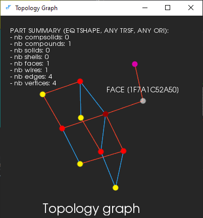
The color codes of nodes denote different types of boundary elements.
| selected | COMPOUND | COMPSOLID | SOLID | SHELL |
| FACE | WIRE | EDGE | VERTEX |
The color codes of arcs denote different topological orientations.
| FORWARD | REVERSED |
To specify the level of details, use the corresponding selector in the corresponding dialog box.
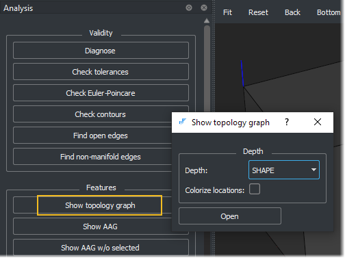
The "colorize locations" checkbox allows one to visualize the internal locations of subshapes.
Why bother?
A topology graph is a low-level thing. You need to work with it, for example, when implementing Euler operators. The topology graph is also a syntactic descriptor of your CAD model that does not specify any geometry. Therefore, if you do some shape editing, you should first ask yourself if it's a topology-only operation (like defeaturing of some isolated CAD features). The topology-only approaches are very efficient and 100% robust if implemented properly.