Recognize drilled holes
The following three types of drilled holes are the most common in industry:
- Simple cylindrical holes.
- Countersunk holes.
- Counterbored holes.
The recognition of these types is important for manufacturing planning, cost estimations, defeaturing, and other computational flows that employ CAD geometry as a data source. In this chapter, we describe the principles grounding the drilled hole recognition.
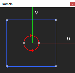
Parametric domain
Since all B-rep faces have their attached UV spaces where all trimming contours are defined, why not take advantage of this data? A quick observation that a cylindrical cutting tool leaves a circular contour on a flat face gives the cue to the possible recognition approach. We first find all the circular loops in the parametric space and then take their diameters as the recognized properties.
Seemingly simple, this approach requires a lot of care to be implemented correctly. Just a couple of things to consider:
- The circles imprinted into the parametric space are constructed by a surface-surface intersection algorithm. Sometimes, depending on whatever reasons, a modeler might prefer creating a spline curve instead of a clean circle. As a result, the recognition attempt based on checking the analytical type of geometry is doomed to fail. To solve that, you should employ a sort of canonical geometry recognition.
- Even with canonical recognition plugged in, you are not secured because:
- Circle fitting is the approximation problem with its inherent inaccuracy. As a result, you will not be able to extract perfect diameters in round numbers. The effects like 6.1 [mm] diameters start to show up.
- Well, sometimes you do not even have circles. For example, the intersection curve between two cylinders (imagine you drill a hole in a round tube) is a Steinmetz curve, not a circle at all. Not to mention other types of objects you drill.
- Composite features like countersunk or counterbored holes could not be captured this way.
Therefore, a more complete and reliable approach would be surface-based feature recognition. While the parametric curves are constructed from scratch by a modeler and are prone to all sorts of dirty surprises, things get much better if you consider higher-dimensional entities, i.e., the faces. When cutting a drilling tool shape from an object shape, the modelers leave the surfaces intact. I.e., if you had a cylindrical cutting tool, you'll get the corresponding cylindrical hole having all analytical properties equal to those of the tool.
The recognition based on parametric curves still has its niche. For example, in sheet metal fabrication, one might classify all cut features as holes and cutouts based on the imprinted curves alone. Once we know that a feature is a cutout, we do not have to process it further as a drilled hole candidate.
Surface-based recognition
The reasons outlined above should leave an impression that a better recognition approach exists for the drilled holes. Indeed, the pragmatic feature recognition approaches rather start from the CAD model's surfaces and not from the edges.
We approach the problem of drilled holes recognition in two stages:
- Extract all isolated groups of faces that look like holes. These faces should have some specific symmetries, such as coaxial cylinders (for counterbored holes) or coaxial cones and cylinders (for countersunk holes).
- Deduce the type of a drilled hole by matching its faces over one of the predefined patterns.
To extract the hole's type together with its properties, we use a dictionary of predefined feature patterns. The following snippet illustrates the dictionary specified via a JSON file, although there could be various ways to organize such a dictionary:
  {
    "patterns": [
      {
        "type": "countersunk-hole",
        "key": "countersunk_01",
        "binbrep": "Ck9wZW4gQ0FTQ0FER...",
        "sinkFaces": [1],
        "holeFaces": [2],
        "blind": true
      },
      {
        "type": "countersunk-hole",
        "key": "countersunk_02",
        "binbrep": "Ck9wZW4gQ0FTQ0FER...","
        "sinkFaces": [1],
        "holeFaces": [2],
        "blind": false
      },
      {
        "type": "counterbored-hole",
        "key": "counterbored_01",
        "binbrep": "Ck9wZW4gQ0FTQ0FER...",
        "boreFaces": [1],
        "holeFaces": [3],
        "blind": true
      },
      {
        "type": "counterbored-hole",
        "key": "counterbored_02",
        "binbrep": "Ck9wZW4gQ0FTQ0FER...",
        "boreFaces": [1],
        "holeFaces": [4],
        "blind": true
      }
    ]
  }
The binbrep property contains the base64-encoded representation of a binary shape. It is essentially a real piece of a CAD model captured by the user (e.g., interactively) and declared as a feature pattern. The recognizer's job then is to derive the pattern's AAG and match it with the AAG of the entire model.
The following image illustrates the anatomy of a complex counterbored feature.
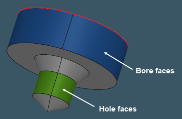
Since all the faces of a pattern feature are labeled a priori, the very possibility to match them with a subset of a CAD model's faces is a key to property extraction.