Reverse engineering overview
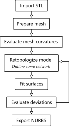
One can think of reverse engineering as a specific CAD modeling process where you start from an existing artifact instead of a blank workspace. The whole process is driven by a reference shape represented with either a point cloud or mesh geometry. Looking from this standpoint, Analysis Situs requires the existence of a reference part guiding the design process and used to snap points, curves, and surfaces. The following figure illustrates a typical reverse engineering workflow.
Reverse engineering might also be named "reverse geometric modeling" or "digital shape reconstruction" to emphasize the fact that this field is focused mainly on modeling. A good starting point for those seeking a theoretical backbone of the reverse engineering techniques is the conference proceedings [Hoschek and Dankwort, 1996].
It all starts with importing a mesh model. The most popular format for unorganized triangulations today is the stereolithography format (STL). Once the import is done, you begin retopologizing your model by outlining the feature lines. The goal of this stage is to build a network of curves bounding the surface patches. It is practical to sketch the boundary curves following the curvature map of your mesh. Once you are done with the topology, it is time to fit surfaces and construct a final manifold shell. In the end, you may want to check the obtained deviation map and export the result to one of the popular CAD exchange formats, e.g., IGES or STEP.