Introduction to CAD feature recognition
Motivation
Form features or simply features are groups of CAD faces or volume elements that are meaningful for a specific engineering activity or application. In most cases, design and manufacturing features are not the same things because a CAD part is not modelled (digitally) the same way it is manufactured. Regardless of its type, a feature is a carrier of domain knowledge associated with the geometry of a part. A cornerstone problem for bridging CAD and CAM software is how to match form features with the corresponding machining programs. We recommend our readers to familiarize themselves with the paper by [Wu et al, 1996] that gives a clear introduction to the feature recognition area of research.
Although it might be possible to design a CAD part in terms of its ultimate manufacturing features, such an approach is not widely used and is generally considered a bad idea [Vandenbrande and Requicha, 1993]. Therefore, even when the design features are known from the originating CAD system, they have to be converted to the manufacturing features to generate NC code. Then, more often than not, the design features are not even available because of lossy data exchange between the employed CAD and CAM packages. As a result, feature recognition had become a fundamental problem in the computer-aided design field.
There is a bunch of engineering workflows where feature recognition is highly demanded. Some of them are listed below:
- Manufacturability analysis. Before passing a CAD part to a machining shop, one has to be sure that this part can be fabricated in the first place. The manufacturability analysis can be conducted to assess all holes, pockets, slots, fillets and chamfers on a CAD part for accessibility and fitting the manufacturing constraints.
- Direct editing. Direct editing is opposed to history-based editing in the sense that direct editing operations (push/pull, face tweaking, etc.) do not rely on the availability of design features somewhere in a feature tree. Instead, direct editing operators perform local feature recognition in the affected area. Knowing local features allows for changing the part's geometry without corrupting its original design intent.
- CAD part simplification (defeaturing). Strictly speaking, simplification (or "defeaturing") is yet another type of direct editing. Simplification is often used to prepare design models for numerical simulation or consumption by downstream systems that do not speak the "CAD language" natively (e.g., for gaming engines). To simplify a feature (e.g., to removal a drilled hole), one needs to recognize that feature in the CAD part in the first place.
- Manufacturing cost estimation. Digital manufacturing (or "Manufacturing as a Service") is a growing industry. It is often necessary to assess the expected production costs for a CAD part before placing the order. Those costs would naturally include the milling, turning or 3D printing time that highly correlates with the part's features. Therefore, feature recognition is required for accurate machining time estimation.
- Manufacturing planning. Even if the design features are known from the originating CAD system (and that is often not the case), automated CNC manufacturing would require specific manufacturing features instead of "form" as-designed features.
To our knowledge, Analysis Situs is the first, and the only open-sourced CAD software aimed to provide general feature recognition functionality.
Why naive approach is not the best?
By "naive" approach we mean the technique of iterating CAD model's faces and grouping them together to compose the features. Such scanning approach is not completely desperate, and, if implemented wisely, it can end up with a workable solution.
At the same time, such a naive approach is fundamentally "blind" as here we do not employ any formalism to ground our recognition algorithm upon. What we do here is just visiting all the CAD faces and analyzing their analytical properties to deduce if they "look like a feature" or not. The following subsections uncover the principal complexities of the recognition process.
It is relatively easy to extract all plain cylindrical holes out of a CAD model if you are well equipped and know how to program (Python can be just fine, although we prefer C++ here). The things get more laborious if you need to distinguish between plain, countersunk, counterbored and counterdrilled holes.
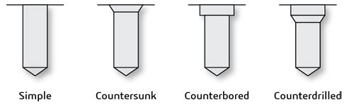
Looking at the image above, you can imagine a few more combinations of countersinks and counterbores, including variations of blind and through holes. The number of possible feature patterns is quite big even for such a simple thing as a drilled hole. Now imagine that these holes perforate each other:
Even without interactions, some holes could not be easily classified as they correspond to a sequence of milling operations, such as boring stacked up steps:
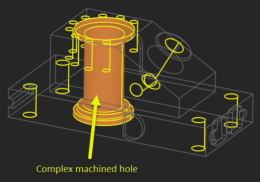
In the presence of interacting and complex features, simple scanning technique becomes error-prone unless it is equipped with a rich set of topologic and geometric checks all applied following some specific recognition strategy. Elaborating such a strategy is not a trivial exercise, although the heuristics employed down the road might not be that complicated.
The principal data structure guiding feature recognition is, of course, the boundary representation of a CAD part itself. Since Analysis Situs is based on OpenCascade, we employ its minimalistic B-rep structure that does not support neither user-defined attributes nor convenient methods of iteration (such as back-references and circulators). Therefore, a computationally efficient feature recognition algorithm should employ some extra data structures, such as:
- Attributes holder. This data structure is aimed at storing all the geometric cues and "knowledge" about the CAD features as they are being extracted by the recognition algorithms progressively.
- Adjacency graphs. These graph data structures allow us to focus on the topological relationships between the boundary elements (and possibly features) and formalize the connectivity of shapes without much care of their geometry.
- Iterators. It is critical to have efficient iterators over the B-rep elements to be able to query, for example, all parent faces for the given edge.
Having a rich B-rep modeller under the hood of a feature recognizer is essential not only because we need to represent a part's shape with all its boundaries. Besides that, we also need to ask various "geometric questions" in the course of recognition. Therefore, we have to leverage the modelling kernel's API to solve the recognition problem.
A sound idea is the key ingerient to any geometric algorithm. If a good idea is missing (and that is often the case with naive scan approaches), the algorithm has good chances to become a "big ball of mud" [Foote and Yoder, 1997], i.e. a piece of puzzled non-maintainable code.
Many scientific papers and technical reports have been published with the aim to document a well-proven feature recognition method. One of such methods consists in injecting the formalism of graph theory aimed at building up the graph-based abstraction of the recognition problem. The driving idea here consists of converting the geometric representation of a CAD part to a pure topological representation which facilitates computation.
Graph-based feature recognition
Introduction
Analysis Situs is mainly focused on graph-based feature recognition. In this graph-based recognition method, the initial B-rep model is enriched with a supplementary descriptor named Attributed Adjacency Graph (AAG). You can read more about the benefits of using graph formalism in our paper [Slyadnev et al, 2020].
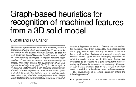
AAG was introduced as a concept back in eighties. You can read a paper by [Joshi and Chang, 1988] where they describe how an adjacency graph can help in the recognition of subtractive features, such as slots or steps.
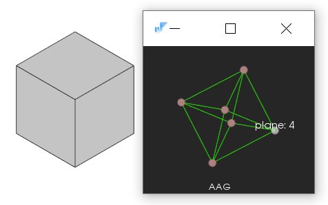
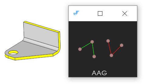
AAG captures the neighborhood relation between the CAD faces. It does not matter how many edges the given two faces have in common: it the terms of adjacency, the graph nodes corresponding to those faces will have exactly one undirected arc in between. Then, there are attributes on the graph. The minimal information required for feature recognition is a Boolean flag indicating if the corresponding dihedral angle is concave or convex. The following image illustrates AAG of a box shape. We use a color code to denote the dihedral angle type (green for convex and red for concave).
People apply different techniques for feature recognition. You're not obliged to use AAG. A more simple technique would be scanning your model like we mentioned before, and this way to use the same neighborhood relations between the B-rep entities without abstracting them to a graph structure. Iterating through B-rep faces, you can consult the types of surfaces, the corresponding normal fields, orientations, etc. Such techniques are based on programmatic rules (C++ logic) and do not take advantage of graph formalism in explicit form. The main reason of introducing AAG in Analysis Situs was to abstract topology from geometry and this way switch from geometry to the language of graphs. In the terms of graph theory, a feature is then a subgraph of an AAG.
The idea of graph-based feature recognition is finding features as subgraphs of AAG. This is basically what Analysis Situs was originally designed for: adding feature recognition logic on top of OpenCascade kernel. The following tools of graph theory become available with an AAG at hand:
- Finding isomorphous subgraphs.
- Analysis of connected components.
- Virtual (topology-only) defeaturing done barely of a graph without affecting the model.
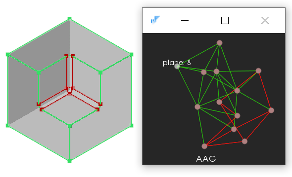
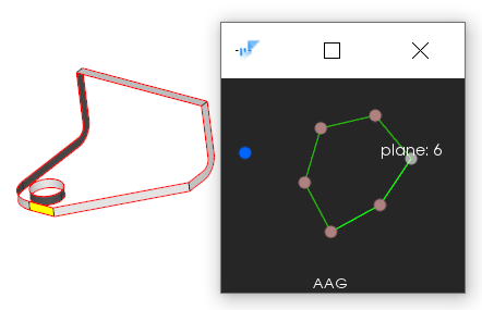
The following image illustrates an application of AAG to the recognition of sheet metal parts. We can exploit the fact that removing all thickness faces in a part separates the graph onto two connected components corresponding to the upper and lower sides of a two-sided part.
In the same way, if we keep only the thickness faces in the graph, we will see a specific circuit pattern in the corresponding subgraph. We can then check if each node of the graph has two incident arcs and the ring is closed. If so, we can conclude that we found a train of thickness faces.
Each node of the AAG has a 1-based index corresponding to the index of a face in Analysis Situs. AAG is represented with an adjacency matrix.
Feature recognition output
If we managed to find a subgraph of AAG corresponding to a certain feature, we should be able to output it as a result. A feature is essentially a set of indices that can be easily serialized to any persistent storage, e.g., a file.
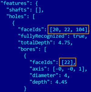
Keep in mind that any modification of the input geometry invalidates the reported indices. However, if you do not modify your geometry, the feature indices are guaranteed to stay the same on loading/writing your CAD data from/to file.
AAG API
To construct AAG, use the ctor of asiAlgo_AAG class passing there the TopoDS_Shape data structure as an argument. At construction time, the AAG will index your topology to assign a unique 1-based index with each face. Other exploration maps can be requested by explicit invocations, such as of asiAlgo_AAG::RequestMapOf*(). At construction time, the graph is build and the dihedral angle attributes are associated with the graph arcs.
AAG is constructed on a heap memory. As you can see, it is a handled class, i.e., it is manipulated by the OpenCascade handle. Once the AAG handle goes out of scope, it decrements the reference counter in the AAG object, and the graph is automatically destructed. This means that you're not supposed to call the destructor explicitly.
It should be noted that any geometric modification done on your CAD model invalidates its AAG. E.g., if you remove a feature from your part, you should forget about the existing AAG and construct a new one. Therefore, AAG is valid as long as your CAD geometry remains "frozen."
In the terms of code architecture, a good practice would be to pass the same instance of AAG through all recognizers you happen to implement in your software: e.g., the recognizers of drilled holes, chamfers, fillets, etc., would all work on the same instance of the graph.
To access the initial shape from AAG, use its asiAlgo_AAG::GetMasterShape() method. You can always dump the contents of your AAG to a text stream calling its asiAlgo_AAG::DumpJSON() method.
std::string filename = "C:/tmp/dump.json";
std::ofstream filestream(filename);
//
if ( !filestream.is_open() )
  return 1; // Error.

aag->DumpJSON(filestream);
filestream.close();
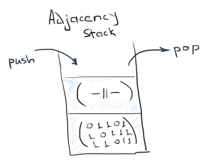
The AAG data structure stores a stack of adjacency matrices representing its states. This stack allows for temporary reducing the entire graph to subgraphs. For example, if you want to keep only specific nodes in the graph, you can use the push/pop API provided by AAG.
The following code demonstrates how one can extract all connected components in a subgraph represented by feature variable. In the code below, the feature indices are selected arbitrarily. In reality, these indices could come from some other recognition algorithms or even be selected by the user interactively.
asiAlgo_Feature feature;
//
feature.Add(10);
feature.Add(20);
feature.Add(13);
// ...

aag->PushSubgraph(feature);
{
  std::vector<asiAlgo_Feature> ccomps;
  aag->GetConnectedComponents(ccomps);

  // Iterate the connected components.
  for ( const auto& ccomp : ccomps )
  {
    // Do something...
  }
}
aag->PopSubgraph();
The asiAlgo_AAG::PopSubgraph() invocation restores the previous state of the graph available on the stack. This push/pop pair of functions is pretty instrumental as it allows to capture only the faces of interest and then undo the modification.
To iterate over AAG, you can use one of the available subclasses of asiAlgo_AAGIterator. The following code illustrates how to iterate all the faces in the graph. For each face, we also check its neighbors in the loop using the asiAlgo_AAG::GetNeighbors() function.
for ( asiAlgo_AAGRandomIterator it(aag); it.More(); it.Next() )
{
  const int              fid  = it.GetFaceId();
  const asiAlgo_Feature& nids = aag->GetNeighbors(fid);
  // ...
}
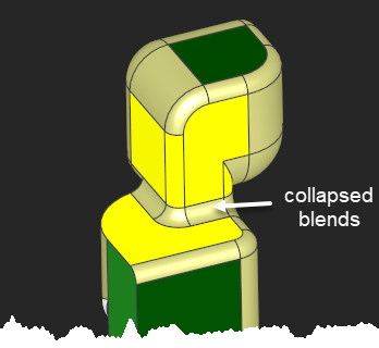
If you want to virtually suppress some faces in the AAG while keeping the incident arcs stitched, use asiAlgo_AAG::Collapse() function. This function is useful if, for example, you want to check the neighbor faces across blends and chamfers while ignoring the latter (see the image below).