Geometric tolerances
Maintaining high-fidelity B-Rep is a challenge. Geometric modeling kernels, such as OpenCascade or Parasolid, implement "tolerant modeling" approach. I.e., instead of using a global geometric inaccuracy, each boundary element (vertex, edge and face) has its own associated imprecision value called [geometric] tolerance.
"Tolerant modeling is a foundation on which reliable solid modeling can be built. By attaching local tolerances to faces, edges and vertices, the boolean algorithm can perform intersections and coincidence tests to appropriate tolerances, and take advantage of a richer structure to represent the resulting solid." [Jackson, 1995]
A visually fine B-Rep model may contain significant geometric flaws like small gaps between faces or wild parameterization of curves. Since what you see on a display is not the real shape but only its faceted approximation, such imperfections remain hidden unless your modeling engine suddenly stops working on downstream operations. Geometric inaccuracy is a nightmare for modeling operators. While there is a certain challenge in how (and to which extent) to maintain tight geometric tolerances, the must-have feature which is relatively easy to implement is the visual checker of those tolerances. The idea is to colorize the boundary elements with respect to their local tolerances. The obtained color mapping gives a good insight on how watertight your model is.
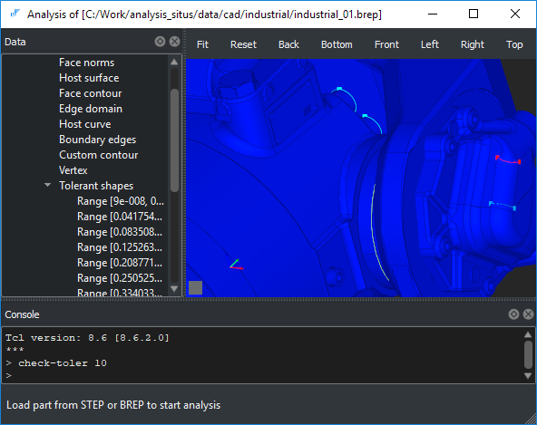
To check tolerances in Analysis Situs, you may use command check-toler. This command creates a certain number of tolerance intervals to colorize the shape. "Warmer" colors mean less accuracy of the corresponding boundary elements.
Whether your tolerances are Ok or not is a tricky question. It has been agreed quite a while ago that the consistency of tolerance definition can be discussed only in the context of a specific application (for reference, see the panel discussion at [Hoschek, 1991, pp. 264-265]). The whole idea of CAD is not to generate mathematically ideal shapes but to make those shapes serve the industry. Therefore, quite often even poor tolerances are anough to mill a part or to generate a finite element model. However, you may face unpredictable problems down the road, e.g., when communicating your CAD model to another software. Thus, even though no model is perfect, it is practically more safe to have as tight geometric tolerances as possible.
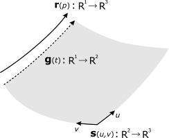
Inaccuracies are often observed at the edges of B-Rep models. There may be a small gap between faces which needs to be shielded by a sufficient tolerance value to make that gap "invisible" for the modeler. Another subtlety is due to the dual edge representation which is a parametric curve living in the two-dimensional space of a host surface (check the figure above). The parametric curve (pcurve) should have synchronous parameterization with the primary curve in 3D. If not, the deviation is also covered by a tolerance value. An asynchronous dual representation often remains invisible because it is not necessarily accompanied by any gaps in 3D. Keeping both representations of an edge consistent is a fundamental requirement for any geometric kernel which employs pcurves.