CAD assemblies
Motivation
We don't have many design options in boundary representation: any CAD model is made up of vertices, edges, and faces. Assembly representation, on the other hand, is frequently application-dependent because it expresses not only a shape but also certain domain knowledge. Attempts to create general representation schemes for CAD assemblies resulted in verbose standards like STEP, PRC, JT, and others.
A comprehensive data scheme covers many aspects of a digital product representation, such as versioning, design review notes, configurations, and so on. While such a rich data model is required for enterprise apps, geometry-centric CAD workflows do not need all of these possibilities. In Analysis Situs, we designed the architecture for CAD assemblies based on the following simple requirements:
- In-memory access. Data should be available in memory for efficient algorithms. In some cases, such as when working with huge CAD assemblies, you cannot save everything in RAM and might prefer serializing data to files or databases. We leave such scenarios out of scope.
- Extensibility. The data framework should offer extension points, allowing client applications to contribute domain-specific data. Consider all types of metadata, including the previously mentioned design review notes. A good data model should not crumble when a new object type is introduced.
Both requirements can be satisfied if the assembly model is based on OCAF/XDE which is the design choice of Analysis Situs. In what follows, we introduce the key data types used when working with assemblies.
Entities
Part
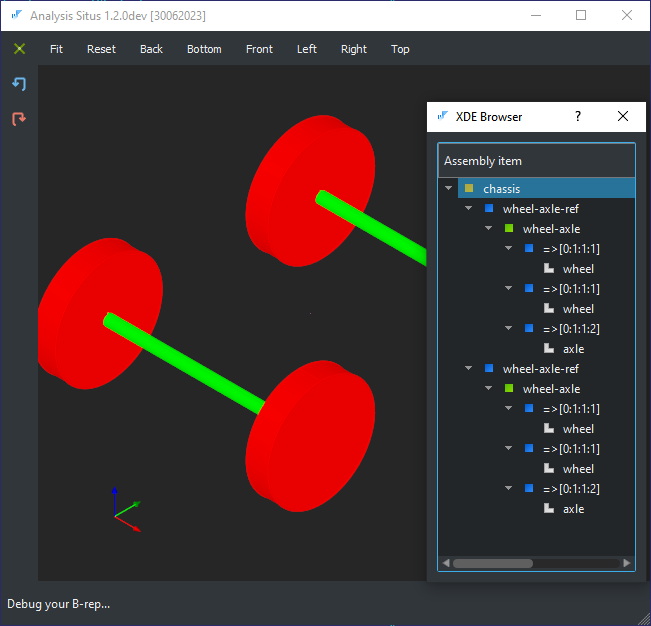
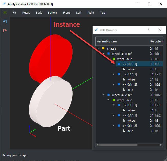
The first entity type that represents a true geometric primitive is a Part. A Part, on the other hand, is not required to contain any geometry. It may also contain multiple visual representations, such as a single bolt associated with varied levels of detail (LOD). Parts are instanced in the assembly structure, which implies they might have several occurrences in the modeling space.

Subassembly
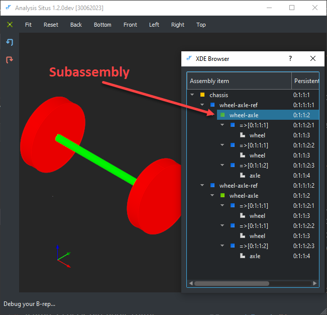
A Subassembly is a composite unit containing references (Instances) to several Parts or nested Subassemblies (recursive definition).
Instance
An Instance is a reference to a specific Part or Subassembly. An Instance is contained within a Subassembly, which has Instances as child elements. Think about an Instance to be a pointer in a computer language.
Prototype
Anything that can be instanced is a Prototype. In other words, it is either a Part or a Subassembly. We use the term "prototype" to refer to reusable units in the assembly structure.
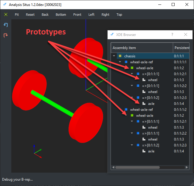
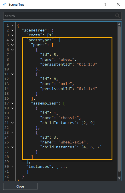
If Instance is a "pointer," then Prototype is the actual thing it points to. All Prototypes can be arranged into a plain list that may be viewed as a bill of materials. The following view is the JSON representation of the assembly structure in Analysis Situs: